3 dc inter-bay copper, 4 battery terminations – Alpha Technologies Cordex CXPS-D 48-2500_5000A User Manual
Page 17
-5HY%
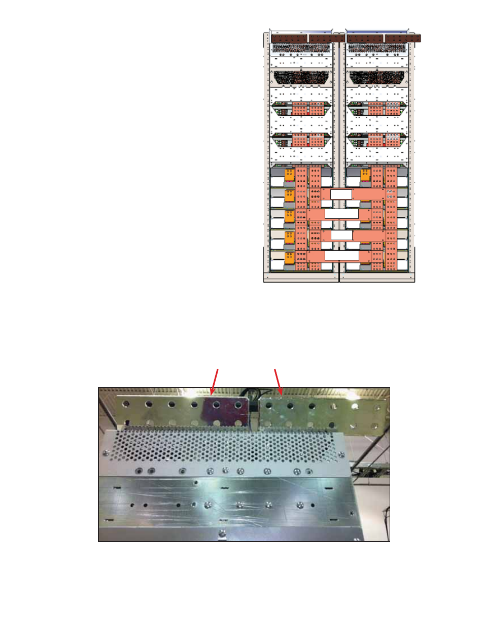
3.3 DC Inter-bay Copper
The inter-bay bus bar is available in 2500 A
nominal sizing. All inter-bay bus work is contained
within the system racks.
Hot Bay Expansion
An additional bay can be added to the system
while online without shutting down the DC plant.
Review Section "1. Safety" on page 7 before under-
taking this procedure.
3.3.1 DC Return Bus Bar
Each power system bay has two vertical distribu-
tion buses sized to carry the required current (see
Figure 2):
The DC inter-bay return bar runs horizontally
across the back of the rectifier shelves intercon-
necting the vertical return distribution buses in
each bay. The return bus bar is the termination
point for load returns, battery returns, rectifier
positive, and site reference ground.
3.3.2 -48 V Bus Bar
The -48 Vdc inter-bay bar also runs horizontally
across the back of the rectifier shelves intercon-
necting the vertical -48 Vdc distribution buses in
each bay.
)LJXUH ² ,QWHUED\'&FRQQHFWLRQVUHDUYLHZ
5HWXUQ
5HWXUQ
9
9
3.4 Battery
Terminations
There are 6 battery termination points (1/2" on 1 3/4" centers and 3/8" on 1" centers) per polarity on each power
system bay (12 termination points if connections are made both front and back).
5HWXUQ
9
)LJXUH ² %DWWHU\WHUPLQDWLRQUHDUYLHZ