8system startup – Alpha Technologies Te41, 24V User Manual
Page 33
Argus Technologies Ltd.
057-102-C0 Rev B WC
Printed in Canada. © 2009 Argus Technologies Ltd. ARGUS and CORDEX are trademarks of Argus Technologies Ltd. All Rights Reserved.
Page 21 of 26
8
System Startup
After completing the enclosure installation and power system wiring, perform the following startup and test
procedure to ensure proper operation:
8.1
Check System Connections
x Ensure AC power is off, batteries are disconnected, and all power modules are removed from the rectifier shelf.
x Triple-check the polarity of all connections.
8.2
Verify AC and Power the Rectifier Shelf
x Install one power rectifier module.
x Verify AC input voltage is correct and turn on the corresponding feeder breaker.
x The power module OK LED should illuminate after a preset start delay.
x Using the CXCM4, test functionality of various module alarms and controls.
8.3
Check Battery Polarity and Connect
x Verify correct battery polarity using a voltmeter (ensuring no cells or batteries are reversed).
x Connect batteries as required to the output of the system.
x Install remaining power rectifier modules.
x In the adjustments menu of the CXCM4, set float and equalize voltage to the levels specified by the battery
manufacturer.
x Using the CXCM4, test functionality of various module alarms and controls. In addition, perform a load test
with the system using a resistive load box as needed.
x Enable the temperature compensation (temp comp) feature (Batteries menu) and program the settings for
slope and breakpoints (upper and lower) with respect to the specific batteries being used.
x Energize air conditioning unit.
8.4
Recommended Temperature Compensation Settings
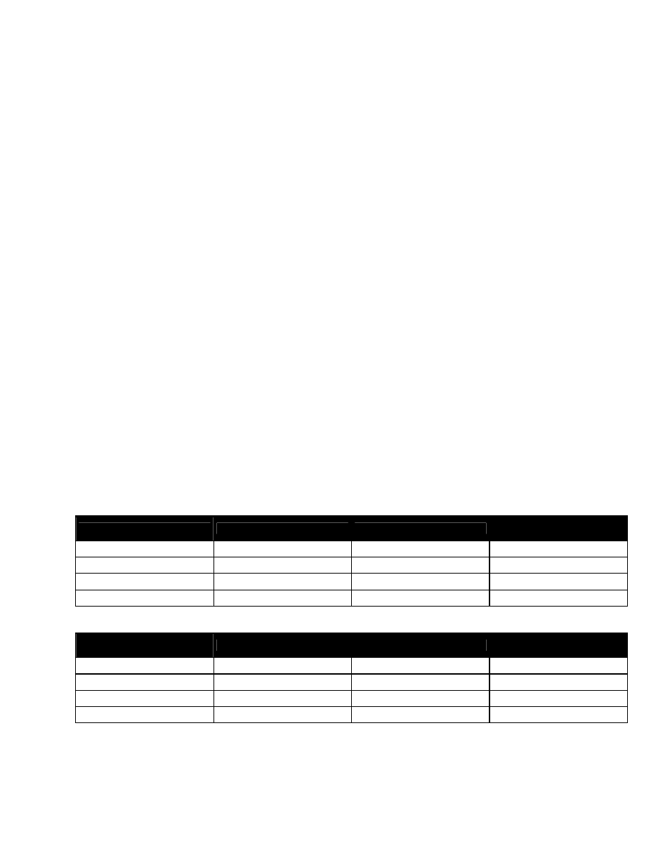
If equipped, enable the temperature compensation (temp comp) feature (Batteries menu in Argus system
controller) and program the settings for slope and breakpoints (upper and lower) with respect to the specific
batteries used as shown in the following tables:
Description
Alphacell SMU-F
GNB Marathon FT
DEKA Unigy 1
All except for 12AVR-100ET
Float V @ 25
qC
27.12V
27.24V
27V
TC Upper Limit
60
qC @ 26.04V
36
qC @ 26.5V
35
qC @ 26.76V
TC Lower Limit
13
qC @ 27.5V
21
qC @ 27.5V
24
qC @ 27.02V
TC Slope mV/cell/C
2.5mV
5.5mV
2mV
Table D–Temp comp settings for 24V system (27.5V max.)
Description
Alphacell SMU-F
GNB Marathon FT
DEKA Unigy 1
All except for 12AVR-100ET
Float V @ 25
qC
54.24V
54.48V
54V
TC Upper Limit
60
qC @ 52.08V
36
qC @ 53V
35
qC @ 53.52V
TC Lower Limit
13
qC @ 55V
21
qC @ 55V
24
qC @ 54.04V
TC Slope mV/cell/C
2.5mV
5.5mV
2mV
Table E–Temp comp settings for 48V system (55V max.)
8.5
CXCM4 Reset
The reset button located on the front panel of the CXCM4 is for restarting the microprocessor. When pressed
momentarily, the unit beeps twice then resets. The front-panel LED’s will illuminate temporarily, but will extinguish
after the system has finished its 15-second self-test.