2 main rectifier modes, 1 output voltage modes, 2 output current/power modes – Alpha Technologies Cordex 48-1.2kW User Manual
Page 34: 3 can bus communications, Main rectifier modes, Can bus communications
030-834-J0 Rev A
Page
28 of 34
6.2
Main Rectifier Modes
In addition to main rectifier states, there is a set of main rectifier modes. These modes are divided into two
categories:
6.2.1
Output Voltage Modes
Voltage modes, under software control, can directly adjust the output voltage. Situations, such as the
rectifier being in current limit, can change the output voltage with no software control.
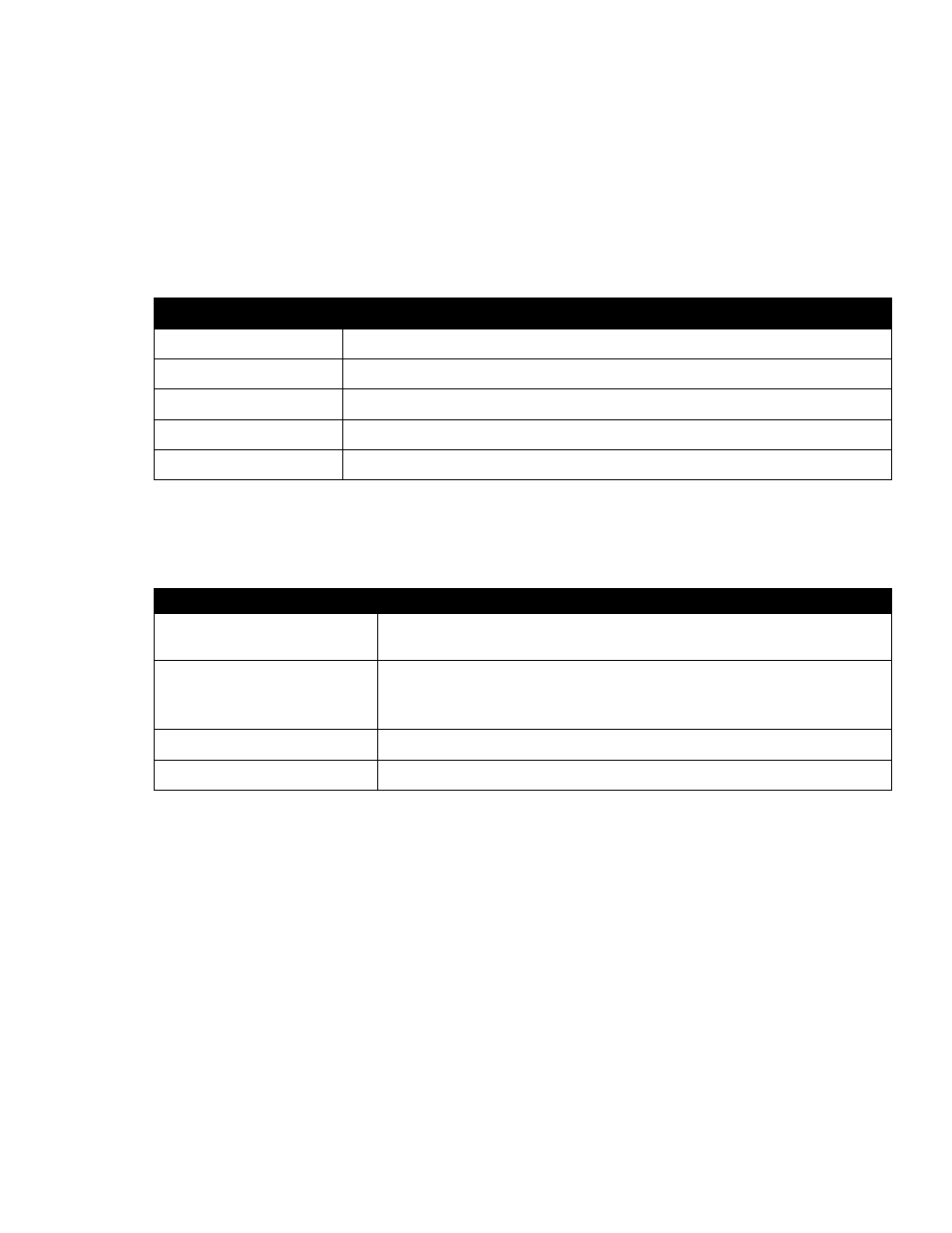
The following table describes the five output voltage modes.
Output Voltage Modes
Active when…
Float
Output voltage is set to the float voltage setting.
Equalize
Output voltage is set to the equalize voltage setting.
Battery Test
Output voltage is set to the battery test voltage setting.
Safe
Output voltage is set to the safe mode voltage setting.
Manual Test
Output voltage can be manually adjusted outside of the standard adjustment
Table C–Output voltage modes
6.2.2
Output Current/Power Modes
These four output current/power modes directly affect the output current and power:
Output Current/Power Mode
Output current and power limit have been reduced due to:
Temperature foldback mode
High temperature of the heatsink or internal ambient temperature sensor.
AC foldback mode
Low AC input voltage.
Note: reduces the risk of tripping an AC breaker due to increased AC
current draw as the AC voltage decreases.
Short circuit foldback mode
Short circuit at the output.
Internal fault foldback mode
Internal fault.
Table D–Output current/power modes
6.3
Can Bus Communications
The CAN bus is used for commands and data transfer between the rectifier and CXC to configure the
rectifier with system settings and to monitor rectifier status.