4 ac input, 5 calculating output wire size requirements, Ac input – Alpha Technologies Cordex 48-1.2kW User Manual
Page 24: Calculating output wire size requirements
030-834-J0 Rev A
Page
18 of 34
5.4
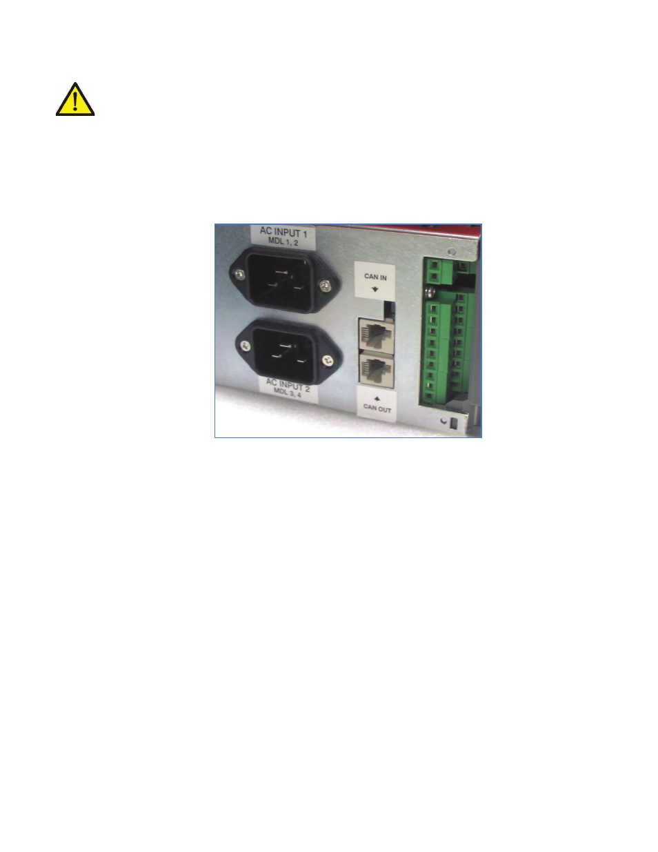
AC Input
CAUTION: Route AC input wires in flexible or rigid conduit as far away as possible from the DC
power wires to minimize EMI disturbances.
All shelf systems have male IEC-60320-C20 ISA line cord connection points for pluggable line cords with
C19R female receptacles as shown in Figure 8.
Refer to customer connection drawings 030-834-08, 030-851-08, 030-835-08 or 030-845-08.
NOTE: The shelf incorporates IEC plug connections requiring line cords with C19R type receptacles. See ordering
information for available cords.
Figure 8–Cordex 48-1.2kW (4800W system) AC input, CAN, and signal connections
5.5
Calculating Output Wire Size Requirements
Wire size is calculated by first determining the appropriate maximum voltage drop requirement. Using the
formula below calculate the CMA wire size requirement. Determine the size and number of conductors
required to satisfy the CMA requirement.
CMA = (A x LF x K) / AVD, where:
CMA = Cross section of wire in circular MIL area
A = Ultimate drain in amps
LF = Conductor loop feet
K = 11.1 constant factor for commercial (TW type) copper wire
AVD = Allowable voltage drop
Check again that the ampacity rating of the cable meets the requirement for the installation application.
Consult local electrical codes (NEC, CEC, etc.) for guidelines. If required, increase the size of the cable to
meet the code.