3 alarm (relay) outputs, Lvd inhibit, 5 lvd control alternative – Alpha Technologies Cordex 48-1.2kW User Manual
Page 32: Figure 13–showing relay connections
030-834-J0 Rev A
Page
26 of 34
5.11.3
Alarm (Relay) Outputs
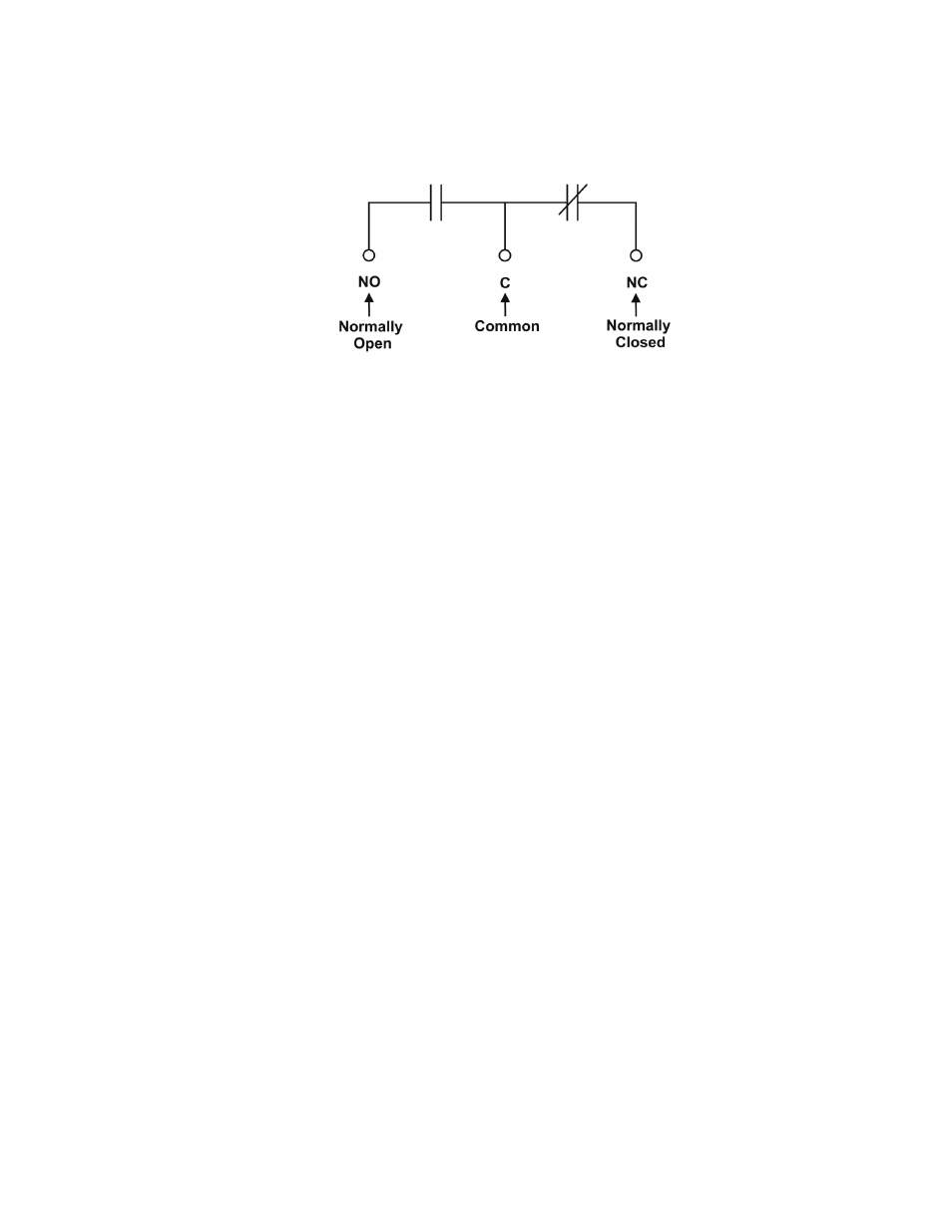
Terminals provide contacts for extending various alarm or control signals. Each relay output can be wired
for NO or NC operation during an alarm or control condition. See Figure 14.
Figure 14–Showing relay connections
Relays can be programmed to energize or de-energize during an alarm condition (see CXC Software
manual). When the CXCM1 reset button is pressed or power is lost, all relays de-energize.
These relays could be used for additional external LVD contactor control; however, this would not provide
the redundant LVD control as with the assigned output pins described below.
5.11.4
LVD Control (Load Disconnect or Battery Disconnect) Option
The disconnect option is controlled by and connected internally to relay K1.
LVD Inhibit
Should it be necessary to remove the CXCM1, the customer connection board (on the front of the shelf)
provides shorting pins (JP2) to inhibit (or override) the LVD Control function. See drawing 030-834-08 next
to TB11, pin 22, of the customer connections.
If the LVD is controlled on NC contacts (factory default for LVD option), then JP2 pins 1 and 2 must be
shorted together to maintain LVD operation. If the LVD is controlled on NO contacts, then pins 2 and 3
must be shorted together. For normal operation, the factory-supplied shorting jumper should be left on pins
3 and 4.
5.11.5
LVD Control Alternative
The LVD Control functions can be hardwired directly from an alarm output relay to an external LVD
contactor (or panel). See Controls Menu Defaults in the CXC Software manual.