Installation – Franklin Fueling Systems T5 Series Density Measurement Option Installation User Manual
Page 2
2
Installation
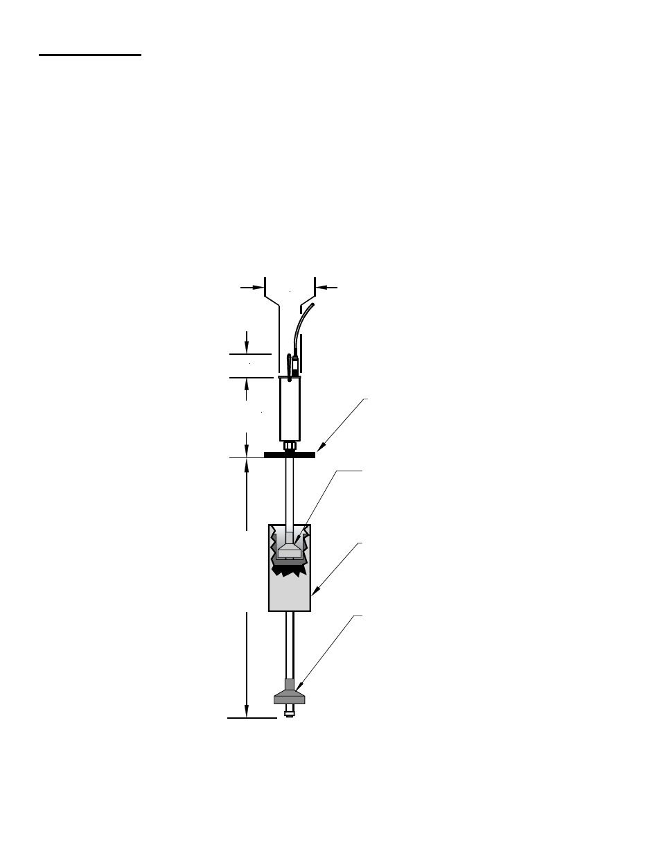
The selection and the installation of the probe is exactly the same as in cases of regular level measurement. The only dif-
ference is in the number and sequence of the floats. To install floats:
Remove the E-ring and washer from the bottom of the probe shaft.
1.
Install the 3" product float on the shaft.
2.
Slide the 4" density float on to the probe shaft with the cylindrical cavity facing the product float and the metal ballast
3.
facing the tip of the probe.
Install the water float if required.
4.
Replace the washer and E-ring that you removed in Step 1.
5.
Record the calibration constant marked on the bottom of the product and density floats. Make sure that both floats
6.
have the same constant.
Do not mix floats from different kits!
Carefully move the floats to the bottom of the probe shaft to prevent damage. The product float should now be inside
7.
of the density float.
2.00"
(50.8 mm)
REF.
2.88"
(73.15 mm)
7.00"
(177.8 mm)
REF.
PROBE
SHAFT
LENGTH
=
MODEL
No. (IN
INCHES)
DENSITY
FLOAT
WATER
FLOAT
(optional)
3" (76.2 mm)
PRODUCT FLOAT
(CUTAWAY VIEW SHOWN)
SPACER
Figure 1
- S940 (8 pages)
- Data Modem / Data Fax Modem for Tank Sentinel, AutoStik, & BulkStik ATGs (1 page)
- Tank Sentinel (TS-1001, 2001, 504, & 508) Setup Programming Guide (184 pages)
- Tank Sentinel (TS-1001, 2001, 504, 508 & 750) Setup Programming Guide (184 pages)
- Main System Board for Tank Sentinel, AutoStik, BulkStik ATGs (4 pages)
- TS-ROM2 (8 pages)
- Memory Backup Battery for Tank Sentinel, AutoStik, & BulkStik ATGs (2 pages)
- Tank Sentinel Quick Reference Guide (2 pages)
- Tank Sentinel (Except TS-2001), AutoStik Jr, BulkStik, AutoStik II (1-4 Ch) Display & Keypad Assembly (P/N 010-0087) (1 page)
- Tank Sentinel (TS-1001, 2001, 504, 508 & 750) Operators Guide Rev. D (100 pages)
- Tank Sentinel, AutoStik, BulkStik Printer Assembly (P/N 020-3050) (1 page)
- Tank Sentinel (TS-1001, 2001, 504, 508 & 750) Operators Guide Rev. C (100 pages)
- Tank Sentinel (TS-1001, 2001, 504, 508 & 750) Installation (98 pages)
- TS-1001, BulkStik, AutoStik (except AutoStik II 8Ch) Ribbon Cable (P/N 600-0077 & 600-0032) (1 page)
- TS-STS Sump Test System Kit (8 pages)
- TS-DTU Noise Suppression Cables TS-DRK (10 pages)
- Console DTU (Data Transfer Unit) (4 pages)
- TS-DTU Data Transfer Unit Dispenser Retrofit Manual (40 pages)
- Colibri One Pulse Relay Rule Setup (1 page)
- Colibri CL6 Installation Guide (12 pages)
- Colibri CL6 Setup and Operators Guide (32 pages)
- Colibri System Board Replacement (2 pages)
- Colibri Quick Reference (2 pages)
- Colibri: Connecting a T5 Series Fuel Management System or Colibri Tank Monitor to an ALVIC SCS3 Point of Sale System (3 pages)
- T5 Series Fuel Management System Installation Guide (30 pages)
- TS-550/TS-5000 consoles Secondary Containment Monitoring (28 pages)
- TS-550/TS-5000 Retrofit Printer Installation (1 page)
- T5 Series Fuel Management System Operators Guide (46 pages)
- T5 Series Fuel Management System Operators Guide (48 pages)
- T5 Series Fuel Management System Programming Guide (66 pages)
- T5 Series Fuel Management System Quick Reference Guide (2 pages)
- T5 Retrofit LCD Display Installation (1 page)
- T5 Tank Sentinel Programming Guide (48 pages)
- TSSP-TMPTR Thermal Printer (8 pages)
- TS 550 evo Fuel Management System Operators Guide (48 pages)
- TS 550 evo Fuel Management System Installation (28 pages)
- TS 550 evo Fuel Management System Quick Reference Guide (2 pages)
- TS 550 evo Fuel Management System Programming Guide (54 pages)
- TS-550 evo MODBUS Installation & Setup (22 pages)
- TS-LLD Changing the TS-LLD Control Unit (1 page)
- TS-LLD Changing the TS-LLD LSU Filter Screen or O-Ring (1 page)
- TS-LLD Leak Detection Sensor – Cleaning & BriteSensor Recovery (2 pages)
- TS-LLD Field Verification : Functional Testing of the INCON TS-LLD (2 pages)
- TS-LLD Changing the TS-LLD Control Unit Faceplate (1 page)
- TS-LLD Changing the TS-LLD 1 microfarad Line Filter Capacitor (1 page)