Controls, indicators, and connectors, Controls, indicators, and connectors -3, 2b asic orien tation – Physio-Control LIFEPAK 20e User Manual
Page 25
2
B
asic Orien
tation
Basic Orientation
LIFEPAK 20e Defibrillator/Monitor Operating Instructions
2-3
©2006-2013 Physio-Control, Inc.
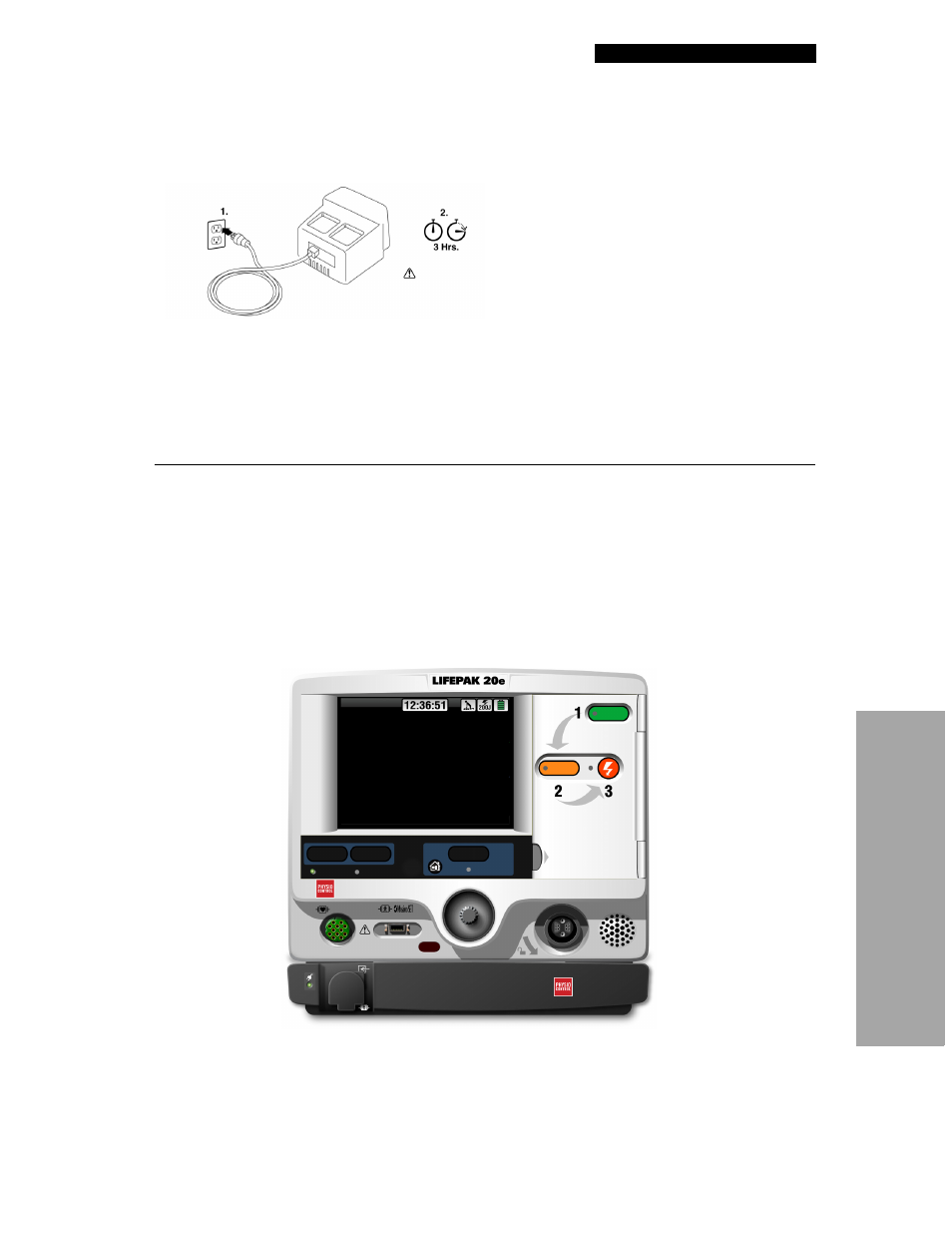
Note the label located to the right of the screen (
). Before the defibrillator/monitor’s first
use, plug the power cord into an AC outlet for 3 hours to charge the internal battery.
Figure 2-1
Initial Battery Charge
If you purchased the CodeManagement Module, you will need to connect it to the LIFEPAK 20e
defibrillator/monitor. Refer to the Installation Instructions provided with the CodeManagement
Module for more information.
CONTROLS, INDICATORS, AND CONNECTORS
The following figures provide a brief description of the controls, indicators, and connectors for the
LIFEPAK 20e defibrillator/monitor and CodeManagement Module.
shows the front
view of the LIFEPAK 20e defibrillator/monitor and
shows the front view divided into
through
show details of each area.
and
show back views of the defibrillator with and without the CodeManagement Module.
Additional information about areas 3, 4, and 7 follow the applicable figures. The light emitting
diode (LED) illuminates (turns on) indicating when the corresponding function is active. For
example, the
ANALYZE
button LED is on when the advisory function is active.
Figure 2-2
Front View with Door and CodeManagement Module
AED Mode
Analyzing Now--Stand Clear
ON
ANALYZE
CODE
SUMMARY
EVENT
ECG
WARNING
DANGER
Hazardous electrical output. For use only by qualified personnel.
Explosion hazard. Do not use in the presence of flammable gases.
AC Mains
Service
Speed Dial
Recommended
Adult VF Dose: XXX-XXX-XXXJ
DEFIBRILLATOR / MONITOR
SpO2
CO2