Rear panels and cabling, A/v input and video output connections, Audio output connections – Extron Electronics System 5 IP Series Setup Guide User Manual
Page 9: System 5 ip hardware setup, Rear panels and cablng, A/v nput and vdeo output connectons, Audo output connectons, System 5 ip switchers • hardware setup
System 5 IP Switchers • Hardware Setup
System 5 IP Hardware Setup
System 5 IP Switchers • Hardware Setup
2-3
2-2
This chapter describes rear and front panel features and basic
front panel operation of the System 5 IP switcher. It shows
you how to connect the cables to audio, video, and control
connectors.
Rear Panels and Cablng
100-240V 1.3A
50-60Hz
Tx Rx G
G
S G S G S G S G
G
Ps
+V
+V
CM IR SCP
R
Y/C
G
Y
B
V
H
VID
Y/C
VID
C
Y
R/VID
G/Y
B/C
H
V
C
VID
V
H
R/VID
G/Y
B/C
INPUT 1
INPUT 3
INPUT 4
INPUT 2
CM/IR/SCP
RS-232
PROJ CONT
A
UD
IO
IR/SERIAL OUT
E
C
B
D
A
L 1 R
L 2 R
OUTPUT
A
L 3 R
L 4 R
B
C
D
1
2
3
4
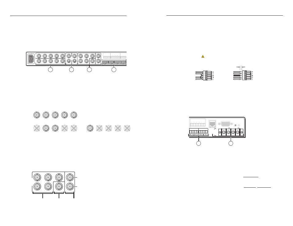
A/V nput and vdeo output connectons
a
Inputs 1 and 2: RGBHV/S-video/composite video inputs
— Connect cables from an RGBHV, S-video (Y/C), or composite
video source to each of these inputs. See the diagrams below.
Inputs must be configured for either video or RGB. See chapters
three, four, and five in the System 5 IP Series User's Manual for
details.
V
H
C
Y
R
/VID
G
/Y
B
/C
V
H
R/
VID
G/Y
B/C
V
H
R/VID
G/
Y
B/
C
RGBHV
Composite Video
S-video
b
Inputs 3 and 4: S-video/composite video inputs — Connect
the cable from either an S-video (Y/C) source (using the 4-pin
mini DIN connector) or a composite video source (using the
BNC connector) to each of these inputs. Inputs 3 and 4 are not
configurable.
c
Display outputs — Cable these output BNC connectors to
an RGBHV, S-video (Y/C), or composite video port on the
projector or display. See the diagram below.
R
G
Y
B
H
V
C
VID
OUTPUT
RGBHV
Composite
Video
S-video
Y = luma
C = chroma
d
Audio inputs — These inputs correspond to the like-numbered
video inputs. For each input, connect the cable from a balanced
or unbalanced stereo or mono audio input source. See the
wiring diagrams below.
N
Do not tin the stripped leads before installing them in the
captive screw connector. Tinned wires are not as secure in
the captive screw connectors and could pull out.
L
R
A
udio
L
R
A
udio
Unbalanced Stereo Input
Tip
Sleeve
Tip
Balanced Stereo Input
Tip
Ring
Sleeve (s)
Tip
Ring
(high impedance)
(high impedance)
Sleeve
CAUTION
For unbalanced audio, connect the sleeve(s) to the ground contact.
DO NOT
connect the sleeve(s) to the negative (-) contacts.
3/16" (5 mm) MAX.
N
After the audio inputs and outputs are connected, refer to
chapter 3, “Front Panel Features and Basic Operation”
and chapter 4, “Software- and Web Page-based Setup and
Control” from the
System 5 IP Series User’s Manual.
Audo output connectons
+
_
LEFT
+
RIGHT
_
2
1
C
C
4
3
C
6
5
C
R
RELAYS
B
A
L LINEOUT R
L PREAMP R
AMPLIFIE
D
OUT
4/8 ohm
CONFIG/RS-232
LAN
1
2
(Amplifier
Models Only)
a
Lineout and preamp audio outputs — Connect an audio output
device to either connector for line level audio outputs. The
lineout and preamp audio outputs are simultaneously active.
Therefore, two devices can be connected at the same time (one to
each output).
•
The lineout connector outputs a fixed level audio signal
that is not affected by audio adjustments.
•
The preamp connector outputs a variable, line level audio
signal for use with a powered amplifier. The volume can
be controlled (attenuated) via the front panel knob, RS-232,
or Ethernet/IP communication. The volume range is 0
(mute) through 40 steps (0% through 100% of the maximum
volume).