System 5 ip hardware setup, cont’d, System 5 ip switchers • hardware setup, 6 system 5 ip switchers • hardware setup – Extron Electronics System 5 IP Series Setup Guide User Manual
Page 11
System 5 IP Switchers • Hardware Setup
System 5 IP Hardware Setup, cont’d
2-6
System 5 IP Switchers • Hardware Setup
2-7
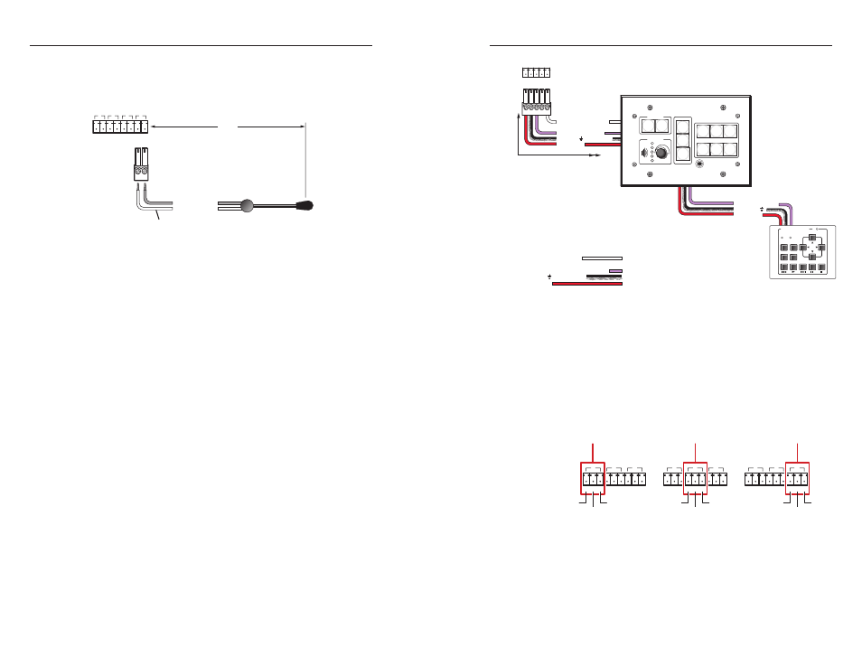
For infrared (IR) output
, wire an IR Emitter (2 emitters,
maximum, per port)
as shown below for a modulated signal
and ground.
S G S G S G S G
IR/SERIAL OUT
A
B
C
D
IR Emitter 1
White Striped Wire
100'
(30.5 m)
G = Ground
S = Signal (IR)
See the System 5 IP Series User's Manual for details on how to set
up these ports for IR or RS-232 control.
c
CM/IR/SCP port
— You can connect up to four Extron control
modules (IRCMs, ACMs, RCMs), one Extron IR Link infrared
signal repeater, and/or up to two Extron SCP 104 or SCP 226
control pads to this port to allow remote control of the
System 5 IP switcher or other items. A maximum of seven
devices can be connected to this port.
The SCP 104 or SCP 226 Secondary Control Panel replicates
most of the switcher’s front panel controls. The control pad
can receive IR signals from an optional IR 402 remote control
and send them to the switcher. Control modules can be used to
control VCRs, DVD players, tape decks, a projector lift, or screen
control. Refer to the appropriate device’s user’s manual.
The control modules, IR Link, and SCPs can be daisy chained,
as shown in the following diagram. Extron CTL (Comm-Link)
cable is recommended for these connections. Use the following
diagram as a wiring guide.
SCP 226
200' (61 m) max.
to Last Device
E
C
B
A
SCP Communication
IRCM, ACM, RCM
+12 VDC
Ground ( ) & Drain Wire
C
B
A
Ground ( )
IRCM/ACM/RCM
+12 VDC
Maximum =
4 Control Modules
(4 Module Addresses)
Control modules include IRCM,
ACM, RCM, and CM models.
DVD & VCR CONTROL
PLAY NEXT/FWD PAUSE
STOP
TUNER
Tx
PREV/REW
ENTER
TITLE
MENU
TV/VCR
DVD
VCR
IRCM-DV+
G
+V
CM IRSCP
E
C
B
D
A
System 5 IP Switcher
Rear Panel
Extron CTL or CTLP Cable Color Code:
Ground ( ) & Drain Wire
E
D
C
B
A
SCP Communication
Modulated IR (for IR Link)
Control Module Communication
+12 VDC
=
White
=
Black & Drain Wire
=
Violet
=
Red
VOLUME
SCP 226
IR
DISPLAY
Extron
1
2
3
4
5
6
ON
OFF
PIC
MUTE
AUTO
IMAGE
PC
VCR
DVD
LAPTOP
DOC
CAM
N
The maximum total distance between the System 5 IP and
a connected device is 200’ (61 m).
N
Extron recommends that you connect the cable’s drain
wire to the ground pin at both ends. This reduces EMI
interference.
d
Relay ports — Via Global Configurator, each relay can be
associated with a front panel button (projector on/off buttons,
function buttons, or input selection buttons) or can be operated
independently.
2
1
C
C
4
3
C
6
5
C
RELAYS
B
A
2
1
C
C
4
3
C
6
5
C
RELAYS
B
A
2
1
C
C
4
3
C
6
5
C
RELAYS
B
A
Group B
Group C
Group A
Common
Relay 4
Relay 3
Common
Relay 6
Relay 5
Common
Relay 2
Relay 1
These relays are normally open by default. They can be
configured via SIS commands or Global Configurator to operate
as follows:
•
on
— relay closes and stays closed until otherwise
instructed
•
off
— relay opens and stays open until otherwise instructed