System 5 ip hardware setup, cont’d – Extron Electronics System 5 IP Series Setup Guide User Manual
Page 12
System 5 IP Switchers • Hardware Setup
System 5 IP Hardware Setup, cont’d
2-8
System 5 IP Switchers • Hardware Setup
2-9
2
1
C
C
4
3
C
6
5
C
B
A
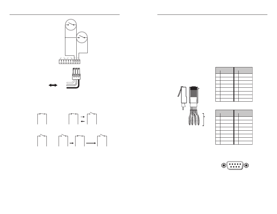
Common
Relay 1
Relay 2
To / from
control
equipment
Nor
mally
Open (1)
Common
Nor
mally
Open (2)
Common
All relays
are
normally
open.
•
toggle
— relay changes from open to closed or from closed
to open until otherwise instructed
•
pulse
— momentary (timed) (press to turn on, timeout to
turn off)
On (Closed)
Common
Off (Open)
Common
Relay On
Relay Off
On (Closed)
Common
Off (Open)
Common
Relay Toggle
or
Toggle off
Toggle on
On (Closed)
Common
Off (Open)
Common
Relay Pulse
Turn off after
a set period
Off (Open)
Common
Turn
on
You can also use SIS commands or Global Configurator to
specify pulse duration.
e
LAN connector and LEDs
— An Ethernet connection can
be used on an ongoing basis to control the System 5 IP in an
Ethernet network.
Use a straight-through cable for connection to a switch,
hub, or router.
Use a crossover cable (ships with the product) for
connection directly to a PC.
•
•
Configure the settings for this port via either SIS commands, an
embedded Web page, or Global Configurator.
LAN port defaults
are as follows:
IP address:
192.168.254.254
gateway IP address:
0.0.0.0
•
•
subnet mask:
255.255.0.0
DHCP:
off
N
If DHCP remains disabled, obtain your System 5 IP
gateway, subnet mask, and IP address from your network
administrator.
Patch (straight) cable
Side 1
Side 2
Pin Wire color Pin Wire color
1 White-orange 1 White-orange
2 Orange
2 Orange
3 White-green
3 White-green
4 Blue
4 Blue
5 White-blue
5 White-blue
6 Green
6 Green
7 White-brown
7 White-brown
8 Brown
8 Brown
Crossover cable
Side 1
Side 2
Pin Wire color Pin Wire color
1 White-orange 1 White-green
2 Orange
2 Green
3 White-green
3 White-orange
4 Blue
4 Blue
5 White-blue
5 White-blue
6 Green
6 Orange
7 White-brown
7 White-brown
8 Brown
8 Brown
Clip Down
Side
1
1&2
3&6 4&5
7&8
234567 8
Pins
12345678
RJ-45
connector
Twisted
Pairs
f
Configuration/RS-232 port
— For switcher configuration and
control via RS-232, connect to the 9-pin HD connector.
RS-232 protocol:
38400 baud
1 stop bit
no parity
8 data bits
no flow control
•
•
•
•
•
•
•
DB9 Pin Locations
Female
5
1
9
6