Control connections, Control connections -5, System 5 ip hardware setup, cont’d – Extron Electronics System 5 IP Series Setup Guide User Manual
Page 10: Control connectons, System 5 ip switchers • hardware setup, 4 system 5 ip switchers • hardware setup
System 5 IP Switchers • Hardware Setup
System 5 IP Hardware Setup, cont’d
2-4
System 5 IP Switchers • Hardware Setup
2-5
Lineout and preamp outputs can both be wired as unbalanced
or balanced (see diagrams below). Only the preamp output has
the -10 dBV/+4 dBu options.
•
Unbalanced, -10 dBV (-8 dBu, 320 mVrms)
— the default,
for consumer level devices such as VCRs, DVD players,
and stereo receivers
•
Balanced, +4 dBu (+6 dBV, 1.23 Vrms)
— for professional
devices such as mixers, signal processors, and power amps
N
Do not tin the stripped power supply leads before
installing them in the captive screw connector. Tinned
wires are not as secure in the captive screw connectors and
could pull out.
Unbalanced Stereo Output
Tip
NO GROUND HERE.
Sleeve(s)
Tip
NO GROUND HERE.
Balanced Stereo Output
Tip
Ring
Sleeve(s)
Tip
Ring
Unbalanced Mono Output
Balanced Mono Output
L
R
A
udio
Tip
NO GROUND HERE.
Sleeve
Tip
Ring
Sleeve
CAUTION
For unbalanced audio, connect the sleeve(s)
to the center contact ground.
DO NOT
connect
the sleeve(s) to the negative (-) contacts.
L
R
A
udio
L
R
A
udio
L
R
A
udio
3/16" (5 mm) MAX.
b
Amplified output (for models with an integrated audio
amplifier only) — The switcher’s internal, 40-watt (20 watts per
channel into a 4 or 8 ohm load) audio amplifier outputs stereo
(default) or dual mono signals on a four-position screw terminal
connected to non-powered speakers. Cable speakers to this
screw terminal for a 20 watts (rms) per channel amplified audio
output.
1.
Use the appropriate wiring for the load as shown in the
following illustration.
+
_
LEFT
+
RIGHT
_
AMPLIFIED
OUT
4/8 ohm
Mono or
Stereo –
Mono or
Stereo +
4 Ohm Load
or
8 Ohm Load
Mono or
Stereo –
Mono or
Stereo +
4 Ohm Load
or
8 Ohm Load
2.
Using the front panel, RS-232, or IP control, set the switcher
for either mono or stereo audio output. That setting affects
the amplified output and the preamp output.
C
Do not short the terminals to ground or the amplifier
will be damaged.
C
Do not bridge the outputs. Bridging could damage
the amplifier.
Control connectons
+
_
LEFT
+
RIGHT
_
2
1
C
C
4
3
C
6
5
C
Tx Rx G
G
S G S G S G S G
G
Ps
+V
+V
CM IR SCP
R
CM/IR/SCP
RS-232
2
PROJ CONT
A
UDIO
RELAYS
IR/SERIAL OUT
E
C
B
B
D
A
A
L LINEOUT R
L PREAMP R
L 1 R
L 2 R
AMPLIFIE
D
OUT
4/8 oh
m
CONFIG/RS-232
LAN
A
L 3 R
L 4 R
B
C
D
4
5
6
1
2
3
7
a
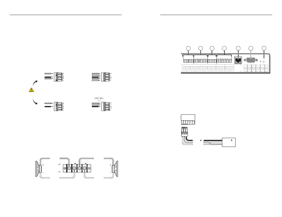
Projector control RS-232 port — Commands from a
downloaded projector driver or user-defined command strings
entered via the Global Configurator program can be sent to the
display device from this port.
For bidirectional communication, the transmit (Tx), ground (G),
and receive (Rx) pins must be wired at both the switcher and the
projector.
Tx Rx G
G
Ps
+V
RS-232
PROJ CONT
System 5 IP
Rear Panel
Projector
Panel
Ground ( )
Receive (Rx)
Transmit (Tx)
Ground ( )
Receive (Rx)
Transmit (Tx)
Bidirectional
N
Each projector or display may require different wiring. For
details, refer to the manual that came with the projector
or click the Comm Sheet button under the Driver
Configuration tab in Global Configurator to display the
"IP Link
®
Device Interface Communication Sheet".
N
Extron recommends the use of shielded communication
cables such as CTL (Comm-Link cable).
b
IR/Serial Output ports — These ports output either infrared
signals or unidirectional RS-232 signals for controlling various
devices such as VCRs and DVD players. Each port must
be set up via Global Configurator for either IR or RS-232
communication and associated with a device driver.