Enclosure – Extron Electronics PowerCage 1600 Enclosure User Guide User Manual
Page 12
PowerCage 1600 Enclosure • Installation
6
Installing Transmitter and Receiver Boards into the Enclosure
Any combination of up to 16 single-slot or 8 double-slot transmitter or receiver boards can
be installed in the PowerCage enclosure. The quantity and type of boards varies depending
on the configuration for each installation site.
Before installing the boards in the enclosure, refer to the model-specific guide for each
PowerCage transmitter and receiver board you are installing. Some boards have switches
that must be set before installation. The guides describe the features of each board and how
to set up and cable it.
NOTE: The boards are hot-swappable; they can be installed or removed without turning
off or disconnecting the power to the PowerCage enclosure.
CAUTIONS:
•
Use ESD precautions when installing a board to avoid damaging it. Keep
the board in the anti-static bag until it is needed.
•
Use proper grounding techniques during installation.
1.
Where applicable, remove as many blank plates or previously installed boards from the
rear of the PowerCage Enclosure as necessary to accommodate the number of new
boards to be installed. Save the screws for use in step 3.
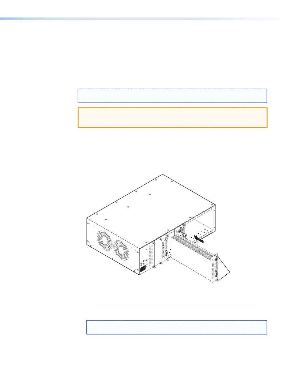
2.
Hold the board with the signal connectors towards you and the LED at the top, and
align the top and bottom grooves of the board with the slide posts in the selected
enclosure slot, as shown in the following figure:
MONO
A
UDIO OUTPUT
12
SHARP
GAIN
Y/VI
D
C
INPU
T
Po
we
rCa
ge
MTP R
AV
Tx
Rx
HD/SDI INPUT
HD/SDI OUTPUT
S
MODE
Po
we
rCa
ge
FO
X 3G HD-SD
I
1
2
REMO
TE
RS-232
RS-232
O
VER FIBE
R
Tx Rx
Tx
ALAR
M
Rx
OUTPUT
RG
B
Po
we
rCa
ge
FO
X RG
B
Tx Rx
LR
A
UDI
O
5A MAX.
100-240V 50/
60H
z
N15
778
C
US
LIS
TED
1T2
3
I.T.
E.
Screws
(2 per board)
1
2
REM
OT
E
RS-232
RS-232
O
VER FIBE
R
Tx Rx
Tx
ALAR
M
Rx
OUTPUT
RG
B
Po
we
rCa
ge
FO
X RG
B
Tx Rx
LR
A
UDI
O
Align board and
slide into slot.
Figure 4.
Inserting Boards into the PowerCage Enclosure
3.
Carefully slide the board into the slot, aligning the two tabs on the lower front end of
the board with the matching ports in the enclosure. Push the board firmly into place.
Tighten the screws to secure the board in place.
NOTE: Use a tool to fully tighten the screws after initial installation and subsequent
removal and replacement of the boards.
4.
Repeat steps 2 and 3 for all boards needing installation.