Video connections, Audio connections, Video connections audio connections – Extron Electronics MTP U T A D User Guide User Manual
Page 14
MTP U T A D • Installation and Operation
8
Video Connections
a
Computer Input connector — Connect a computer (VGA) video source to this 15-pin
HD connector for a high resolution video input.
NOTES:
•
Input only sync signals, no video signals, on the sync pins (13 and 14).
•
For component video, use the R (R-Y) and R return pins (pins 1 and 6),
G (Y) and G return pins (pins 2 and 7), and B (B-Y) and B return pins (pins
3 and 8).
•
For S-video, use the R, R return (C-chroma), G, and G return (Y-luma) pins.
•
For composite video, use the G pin and the associated return pin. For
additional genlocked video signals, use the R, B, and associated return
pins.
b
Monitor Output connector — Connect a video monitor to this 15-pin HD connector
for buffered loop-through of the high or low resolution video input on the Computer
Input connector (
a
) only.
c
YUV (component video) input connectors — Connect a component video source to
these RCA jacks for a high or low resolution component video input.
d
S-video input connector — Connect an S-video source to this 4-pin mini-DIN
connector for a Y/C video input.
e
Video (composite) input connector — Connect a composite video source to this RCA
jack for a low resolution video input.
Audio Connections
NOTES:
•
The Audio Input (mini-jack) audio connector is selected when:
•
The Computer Input video (
a
) is selected for output.
•
The transmitter is in auto switch mode (DIP switch 1 [
h
] is off) and no
active video signal is selected.
•
The Audio (RCA) connectors are selected when:
•
The YUV (
c
), S-video (
d
), or Video (composite) (
e
) input is selected.
•
The selected stereo audio input is summed and output on the TP cable as
mono audio.
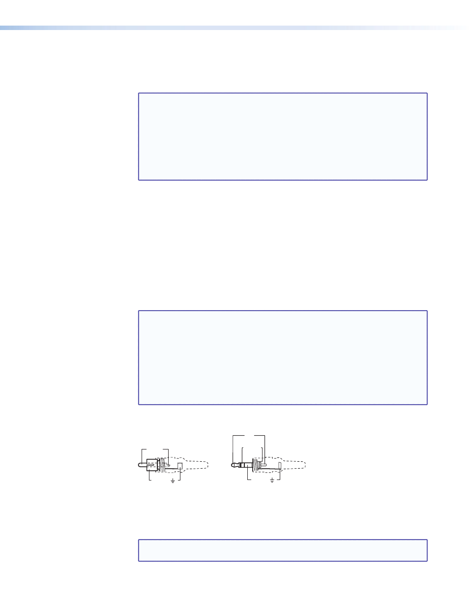
f
Audio (RCA) connector — Plug stereo audio into these left and right RCA jacks for
unbalanced audio input. Wire the plug as shown in
.
Tip (+)
Sleeve ( )
RCA Connector
3.5 mm Stereo Plug Connector
(balanced)
Sleeve ( )
Ring
Right (-)
Tip
Left (+)
Figure 5.
Typical Audio Plugs
g
Audio Input (mini-jack) connector — Plug a 3.5 mm stereo audio plug into this jack
for unbalanced audio input. Wire the plug as shown in
NOTE: Figure 5 shows a typical 3.5 mm audio connector, which consists of a tip,
ring, and sleeve, and an RCA connector, which consists of a tip and sleeve.