Extron Electronics MTP U T A D User Guide User Manual
Page 12
MTP U T A D • Installation and Operation
6
5.
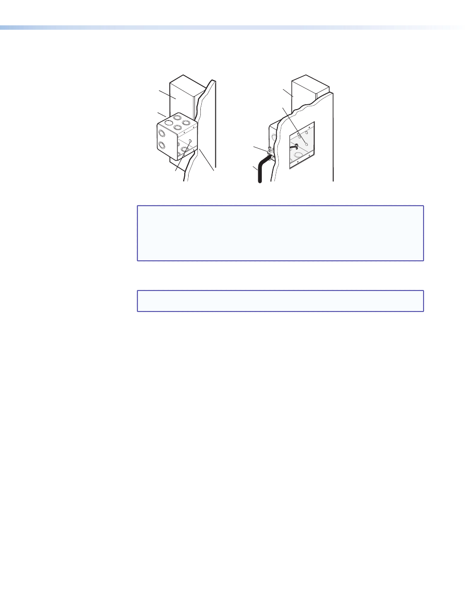
Secure the wall box with nails or screws, leaving the front edge flush with the outer wall
or furniture surface (see
).
Installation
Cable
Cable
Clamp
Wall Stud
Flush with
Wall Surface
Screws or
Nails
Screws or
Nails
Wall Stud
Wall Box
Figure 2.
Installing the Wall Box
NOTE: If attaching the wall box to
•
Wood — use four #8 or #10 screws or 10-penny nails. A minimum of 0.5
inch (1.3 cm) of screw thread must penetrate the wood.
•
Metal studs or furniture — use four #8 or #10 self-tapping sheet metal
screws or machine bolts with matching nuts.
6.
Feed the power cable through the opening and through the wall box punch-out holes
into the box, securing the cable with cable clamps to provide strain relief.
NOTE: In order to fit in the junction box, the TP cable and RJ-45 connector should
not have a boot installed.
7.
Feed the twisted pair cable in through the wall box punch-out holes, securing the cable
with clamps to provide strain relief.
8.
Trim back or insulate exposed cable shields with heat shrink to reduce the chance of
short circuits.
9.
To prevent short circuits, the outer foil shield can be cut back to the point where the
cable exits the cable clamp.
10.
Connect the power cable and TP cable to the rear of the unit (see "
" for connector wiring details).
11.
Connect a video and an audio source to the front panel (see "
for connector details).
12.
Restore the power supply and test the transmitter/receiver system. Make any cabling
adjustments before final installation, as the cables will be inaccessible afterwards.