Serial bridging, Hardware connection, Serial bridge configuration – Extron Electronics IPL 250 Reference Manual User Manual
Page 41: Serial bridging -15
3-15
IPL 250 • Software-based Configuration and Control
Serial bridging
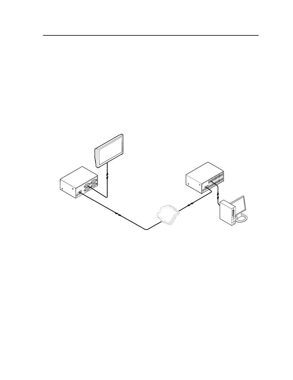
Serial bridging mode creates a virtual serial connection (a “bridge”) between two
IPL units allowing serial data to be passed over a shared LAN to devices connected
via the IPLs’ COM ports. To use serial bridging, two IPL devices (one local and
one remote) must be enabled to communicate with each other, providing PC,
touchpanel, or controller access to a remote A/V device.
Hardware connection
To set up the hardware for serial bridging:
1.
Verify that the protocol (baud rate, data bits, stop bits, parity) is identical for
both serial ports that will be “bridged” (one port on each IPL unit).
2.
For IPL unit 1 (the remote device), connect a serial cable to an A/V device
(e.g., a display or projector).
3.
Connect that same remote IPL (1) to the LAN.
COM
3
LA
N
UID# 093012052
PO
WE
R
12V
.5A MA
X
COM
2
COM
1
COM
2
RS-232
Plasma Display
Unit 1
(Remote)
Unit 2
(Local)
Extron
IPL T S4
Ethernet Control
Interface
Ethernet
INPU
T
LA
N
POWE
R
12V
500m
A
MAX
1
2
3
4
COM
3
IR
3
S
G
S
G
TX
RX
4
RELA
Y
3
4
COM1
TX
RX
RTS CT
S
COM
2
IR
1
S
G
S
G
TX
RX
2
RELA
Y
1
2
Extron
IPL 250
IP Link
®
Ethernet
Control Processor
Remote User Control &
Administrator Monitoring
Ethernet
RS-232
TCP/IP
Network
Connections for serial bridging
4.
For IPL unit 2 (the local device), make a serial connection to the PC or
controller or touchpanel that will control the remote A/V device.
5.
On the same device (2), follow the step 2 instructions.
You are now ready to configure IPL unit 2 for serial bridging mode.
Serial bridge configuration
To allow both IPL units to communicate together, you must configure unit 2 to
communicate with unit 1.
N
If a serial (RS-232) driver was previously loaded (via Global Configurator) onto
the IPL unit, serial bridging disables it.
To configure unit 2 to communicate with unit 1:
1.
Enter the IP address of unit 2 in the Internet browser’s Address field at the
top of the screen, and press the Enter key. The System Status page opens,
showing the current IP and serial port settings of IPL 250 unit 2.
2.
Access the Web server port setting screen by clicking the Configuration tab,
then the Port Settings link on the left side of the window. The Port Settings
page appears, as shown in the following figure.