Rear panel features and connections, Power connection, Rear panel features and connections – Extron Electronics IPL 250 Reference Manual User Manual
Page 20: Hardware features and installation, cont’d
Hardware Features and Installation, cont’d
IPL 250 • Hardware Features and Installation
2-6
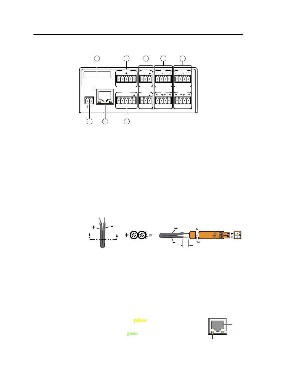
Rear Panel Features and Connections
INPUT
LAN
POWER
12V
500mA
MAX
1 2 3 4
COM 3
IR
3
S G S G
TX RX
4
RELAY
3
4
COM1
TX RX
RTS CTS
COM 2
IR
1
S G S G
TX RX
2
RELAY
1
2
MAC: 00-05-A6-XX-XX-XX
S/N:
1
2
7
3
8
4
5
6
a
Power connector
(page 2-6)
b
LAN (Ethernet, IP) connector
and LEDs
c
COM1 configurable RS-232 port
(page 2-7)
d
COM2 and COM3 RS-232 ports
(
)
e
IR output ports 1-4 (
)
f
Relay ports 1-4 (
)
g
Input (contact input) ports
)
h
MAC address — (
)
Power connection
a
Power connector — To power the IPL, connect a cable between this port and
the included 12 VDC, 1 amp (maximum) power supply. The Extron power
supply included with the IPL is ready to plug in. Wiring is shown in the
following diagram.
Bidirectional control and communication connections
b
LAN (IP) connector and LEDs — To connect and to control the IPL and the
devices connected to it in an Ethernet network, plug a cable into this RJ-45
socket and connect the other end of the cable to a network switch, hub, router,
or PC connected to an Ethernet LAN or the Internet.
• For 10Base-T (10 Mbps) networks, use a CAT 3 or better cable.
• For 100 Base-T (max. 155 Mbps) networks, use a CAT 5 cable.
You must configure this port before using it.
Activity LED
— This yellow LED blinks to indicate
network activity.
Link LED —
This green LED lights to indicate a good
network connection.
2-Pole Captive Screw
Connector
Tie Wrap
3/16”
(5 mm) Max.
SECTION A–A
Ridges
Smooth
Power Supply
Output
Cord
A
A
LAN
RJ-45
Port
Link
LED
Activity
LED