Video adjustment area, Output configuration area, Advanced configuration area – Extron Electronics FOX 500 DA6 User Guide User Manual
Page 25: Remote control, cont’d
FOX 500 DA6 • Remote Control
Remote Control, cont’d
3-20
FOX 500 DA6 • Remote Control
3-21
Video Adjustment area
The Video Adjustment area provides slider controls that let you
change the following video parameters:
• Horizontal shift (position)
• Vertical shift (position)
• Horizontal start
• Pixel Phase
• Total pixels
N
When you make horizontal or vertical position changes
(shift the image), the setting is changed in the receiver(s).
The master receiver reports the shift values to the DA via
the optional Optical 2 cable connected betweeen the DA
and the master receiver.
If your computer is connected to either of the DA's serial
ports, and the Optical 2 cable is not connected between the
master receiver and the DA in your system, you can still
shift the image in the control program's Video Adjustment
area, but the program cannot report the position values.
Output Configuration area
Sync Format radio buttons —
Click either the RGBHV/RGBS or
the RGsB radio button to select the desired video output sync
format.
Output Polarity radio buttons —
Click either the Follow input
sync
or the Force sync to negative radio button to select the
desired video output sync polarity.
N
When you make output configuration changes, the setting
is changed in the receiver(s). The master receiver reports
the changes to the DA via the optional Optical 2 cable
connected betweeen the DA and the master receiver.
If you are connected to either of the DA's serial ports, and
the Optical 2 cable is not connected between the master
receiver and the DA in your system, the program cannot
report the output sync format and polarity position
settings in the control program's Video Adjustment area.
You can change the output sync format and polarity, but
the program cannot report the changes.
Advanced Configuration area
Executive Mode
button —
Click the Executive Mode radio
button to toggle the front panel lock on and off.
N
When you toggle the front panel lock on and off, the setting
is changed in the receiver(s). The master receiver reports
the changes to the DA via the optional Optical 2 cable
connected betweeen the DA and the master receiver.
If your computer is connected to either of the DA's serial
ports, and the Optical 2 cable is not connected between
the master receiver and the DA in your system, you can
still toggle the front panel lock in the control program's
Advanced Configuration area, but the program cannot
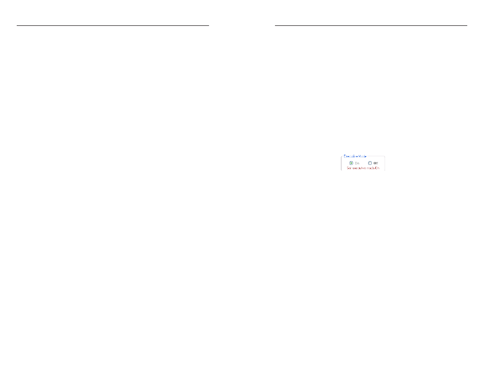
report the lock's status. The program indication changes
(figure 3-6) to show that the Executive mode is control
only, without and indication of the current mode. The
Set executive mode On or Off message is displayed for
approximately 1 second.
Figure 3-6 — Alternate Advanced Configuration area
indication
Auto Memory
checkbox —
Click the Auto Memory checkbox
to automatically apply saved position, horizontal start,
total pixels, and pixel phase settings when the sensed input
resolution changes. See "Auto Memory submenu" in chapter 2,
"Installation and Operation" for more details about the auto
memory function.
Auto Image
button —
Click the Auto Image button to adjust the
output settings for the best image, based on the sensed input
resolution.
Test Patterns
drop box —
Select one of three built-in test
patterns - Color Bars, grayscale, and alternating pixels - as
necessary to help adjust the display's color, focus, and grayscale.
Select Off to output the video input to the DA.
N
You must have a video input connected and fiber cable
Optical 1 connected between the DA and receiver for the
receiver to output a selected test pattern.
The test pattern turns off if the input signal rate is changed
or disconnected, or if power is removed.