Front panel indicators, Installation and operation, cont’d – Extron Electronics FOX 500 DA6 User Guide User Manual
Page 14
FOX 500 DA6 • Installation and Operation
Installation and Operation, cont’d
2-10
FOX 500 DA6 • Installation and Operation
2-11
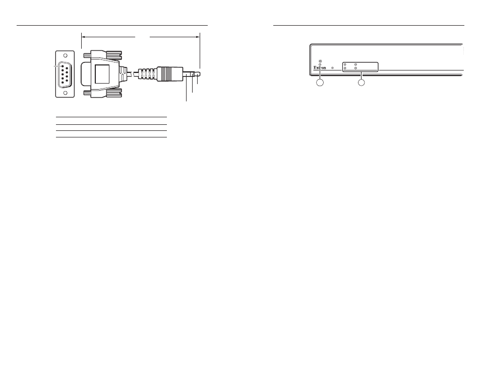
6 feet
(1.8 m)
Part #
70-335-01
5
1
9
6
Sleeve (Gnd)
Ring
Tip
9-pin D
Connection
TRS Plug
Pin 2
Computer's RX line
Tip
Pin 3
Computer's TX line
Ring
Pin 5
Computer's signal ground
Sleeve
Figure 2-9 — Optional 9-pin TRS RS-232 cable
N
This port parallels the rear panel Remote RS-232 ports. If
a front panel configuration connection is made, the rear
panel Remote RS-232 port becomes inactive and the front
panel Configuration port is active.
This port is RS-232 only, with the following protocols:
• 9600 baud
• no parity
• 8 data bits
• 1 stop bit
• no flow control
N
The maximum distances from the DA or receiver to the
controlling device can vary up to 200' (61 m). Factors
such as cable gauge, baud rates, environment, and output
levels (from the unit and the controlling device) all affect
transmission distance. Distances of about 50' (15 m) are
typically not a problem. In some cases, the unit may be
capable of serial communications via RS-232 up to 250'
(76 m) away.
Front Panel Indicators
RGB
AUDIO
LINK 1
CONFIG
LINK 2 (OPTIONAL)
1
2
Figure 2-10 — DA indicators
a
Power LED — This LED lights to indicate the power is
applied to the unit.
b
Signal monitoring LEDs —
RGB LED —
This LED lights on both units when the DA detects
a sync signal on its video input:
•
Horizontal sync (H) (for RGBHV video)
•
Composite sync (S) (for RGBS video)
•
Green (Sync on green) (G) (for RGsB or RsGsBs video)
Audio LED —
This LED lights when the DA detects a low level
audio signal for a short period of time. This LED goes dark if
the audio signal drops below the minimum threshold for a short
period of time.
Link 1 LED
— This LED lights when the master receiver
detects light on the fiber optic cable Optical 1 and the fiber optic
cable Optical 2 is installed between the master receiver and
DA output 1.
N
Only one fiber optic cable, Optical 1, is required for
video, audio, and serial command transmission. But,
if you connect only one fiber optic cable, you do not
receive RS-232 communications from the controlled
device connected to the master receiver, and there is
reduced RS-232 command and Windows control program
functionality on the receiver. To receive responses
from the master receiver and for full functionality,
you must install both fiber optic cables between the
DA and the master receiver.
Link 2 LED
— This LED lights when the DA detects light on the
fiber optic cable Optical 2 connected to ouput 1.