Net Optics iBypass HD User Manual
Page 34
30
iBypass HD
• Heartbeat Mode (mode) – selects whether Heartbeat Packets should be issued from monitor port 1, 2, or both
• Heartbeat Retry Count (retries) – number of times in a row that the Heartbeat packets are missed in order to
trigger Bypass On state; for example, when retries=1, Bypass On is triggered when a single Heartbeat packet is
lost; the value must be in the range of 1 to 10; the default value is 1
• Heartbeat Interval (interval) – number of milliseconds between emitting Heartbeat packets; the value must be
in the range of 1 to 65535; values greater than or equal to 1000 (1 second) are recommended for 1 Gbps bypass
switches; the default value is 1000
• Heartbeat Timeout (timeout) – number of milliseconds to wait for a Heartbeat packet to be returned, before
it is determined to be lost; the value must be in the range of 1 to 65535 and must be less than or equal to the
Heartbeat Interval; the default value is 1000
Use Bypass Switch Pairs in High Availability (HA) Mode
The pair of bypass switches in each DBM can be configured to operate in a HA mode that supports both redundant links
and redundant tools. If you want to operate with both redundant links and redundant tools, choose ha_mode=both.
If you want to operate with redundant links and a single tool, choose ha_mode=link and only the tool set as
primary_tool=<1|2> will be used. To operate with redundant tools and a single link, choose ha_mode=tool and only
the link set as primary_link=<1|2> will be used. Set ha_mode=disable to use the two segments independently, not in
an HA mode.
The following sections describe HA operation when the primary link and primary IPS are active, when the primary link
fails, when the primary IPS fails, and when both the primary link and the primary IPS fails.
HA mode—Normal operation
HA mode enables two links and two IPSs to be connected to a DBM, with the second link and IPS acting as backups for the
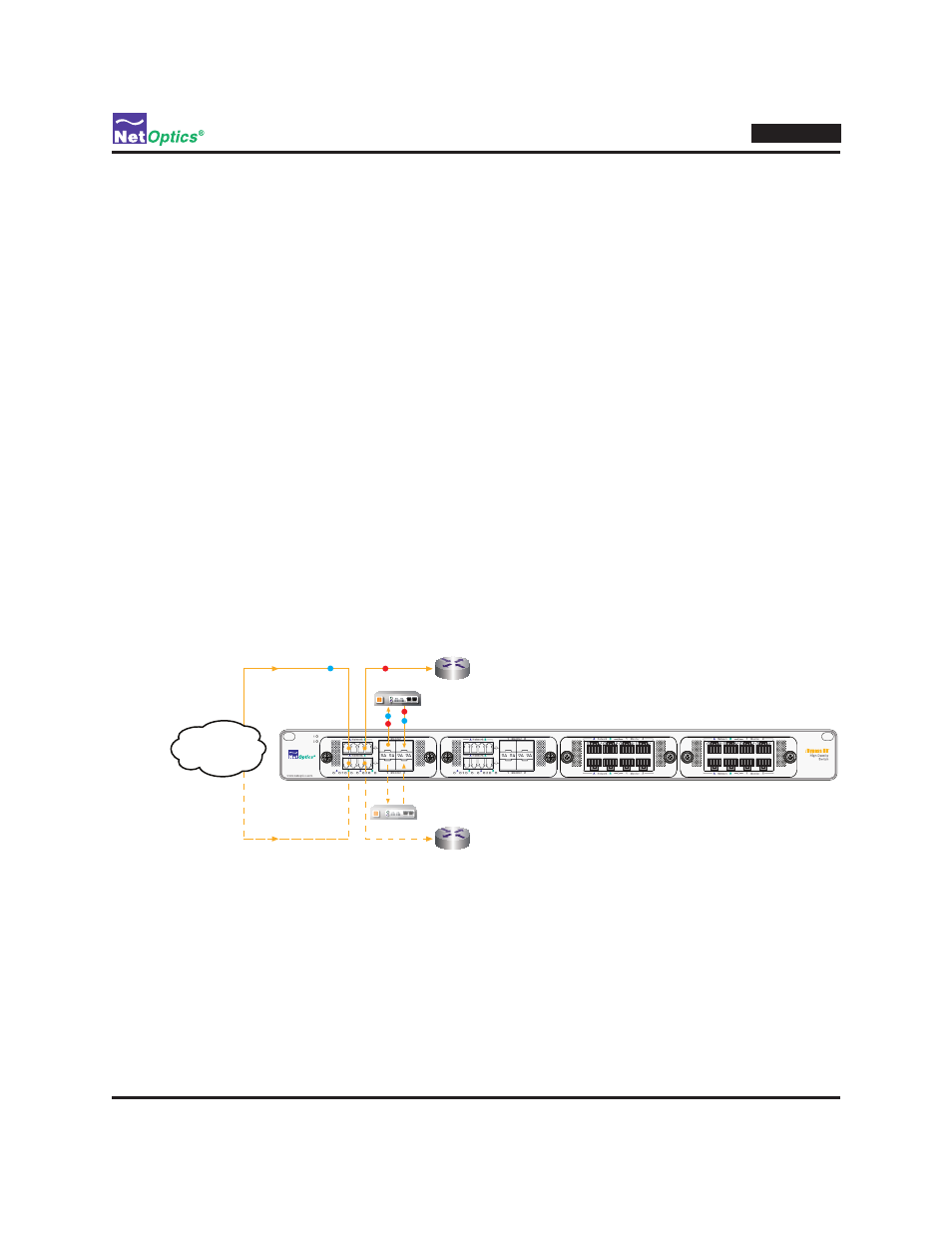
primary link and IPS. Normal operation, when both links and both tools are functional, is shown in the following figure:
Passive link
Active link
Internet
X
IPS
Active link
Active link
Passive link
Internet
IPS
Backup IPS
Backup IPS
Normal Operation
Operation When Primary Link Fails
Backup IPS
IPS
X
Operation When Primary IPS Fails
Passive link
Internet
Passive link
Active link
Internet
X
Operation When Primary Link
and Primary IPS Fail
Backup IPS
IPS
X
Figure 18: DBM 1 operating in HA mode
At the top of Figure 18, traffic is shown flowing on the upper link (segment 1) from the Internet, through bypass switch 1
(the primary bypass switch) and IPS, to the router. (It also flows in the opposite direction.) The lower link (segment 2) is a
backup in case the active link fails; the lower link's path through the bypass switch is in Bypass On mode, so traffic can
flow on the link if there is any traffic moving through the backup path.
A second IPS is installed on the monitor ports of bypass switch 2, to act as a backup in case the primary IPS fails.
Heartbeat packets are sent through the backup IPS because bypass switch 2 is in Bypass On mode.