Net Optics iBypass Switch 1_10_100_1000 Gigabit User Manual
Quick install guide
© 2013 by Net Optics, Inc. Net Optics® is a registered trademarks of Net Optics, Inc. iBypass Switch™ is a trademark of Net Optics, Inc. 800-0191-001 Rev B
Connecting to Network
Do the following to connect the iBypass Switch to your network:
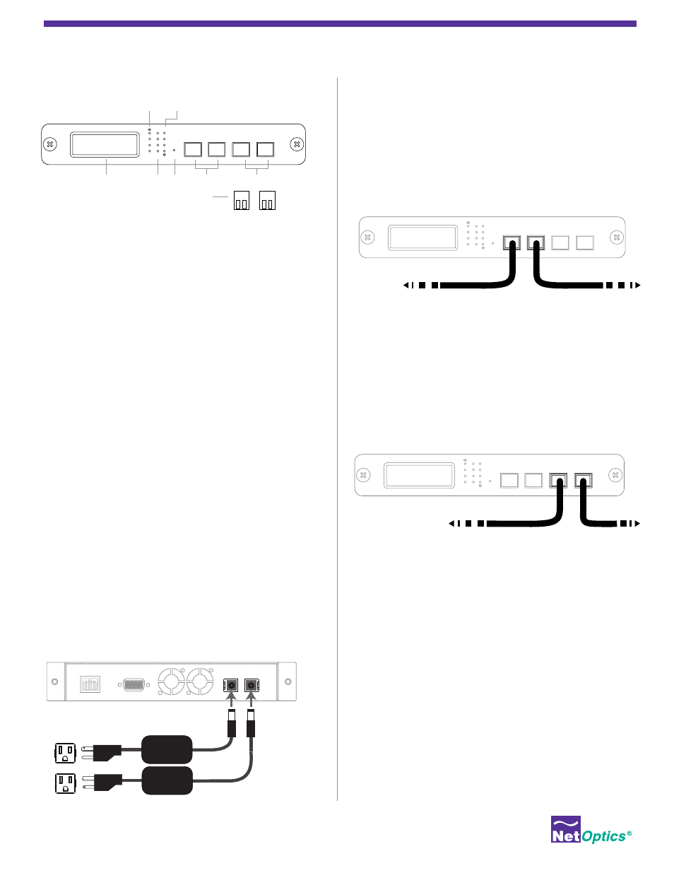
1. Connect Network port A to the appropriate network device
using the cables supplied with your iBypass switch.
2. Connect Network port B to the appropriate network device
using the cables supplied with your iBypass switch.
Connecting to Monitoring Devices
Do the following to connect the iBypass Switch to your monitor-
ing devices:
1. Connect Monitor port 1 to the appropriate NIC using the
cable supplied with your iBypass switch.
2. Connect Monitor port 2 to the appropriate NIC using the
cable supplied with your iBypass switch.
Checking the Installation
After you have connected the iBypass switch, do the following to
verify that the iBypass switch is functioning correctly.
• Check that the power LEDs are illuminated.
• Check the link status and activity LEDs located on the front
panel to verify that the links are connected and traffic is
passing through the iBypass switch.
• Check the LCD for traffic and peak information.
• Ensure that the monitoring device is receiving traffic from the
iBypass switch.
Unpacking
An IBypass switch ships with the following:
• iBypass switch
• Two power supply cords
• Access Products User Guides (on CD)
• Network and monitor cables
• RJ45-to-RS232 DB9 console cable
• 3-meter RJ45, CAT 5e 4-pair
• Maintenance plan, if purchased
• Rack unit panel for rack mounting the switch, if purchased
Carefully check the packing slip against parts received. If any part
is missing or damaged, contact Net Optics’ customer service.
Mounting the iBypass Switch
Do the following to rack mount the iBypass Switch:
1. Attach the two-slot panel to your rack and secure by tighten-
ing the four thumbscrews.
2. Slide the iBypass switch into one of the slots and secure with
the thumbscrews.
3. Make sure that the rack is properly grounded.
Connecting power to the iBypass Switch
Do the following to connect and apply power to the switch:
1. Plug one of the supplied power cords to a power connector
located at the rear of the chassis.
2. Plug the other end of the power cord to a power source.
3. For redundancy, plug a power cord to the iBypass switch.
4. Plug the other end to a power source independent from the
first power source.
The Power LED on the front illuminates.
1 Gigabit iBypass Switch™
10 Gigabit iBypass Switch™
10/100/1000 iBypass Switch™
Quick Install Guide
Management
Port
RS232
1
2
BYPASS
LINK
B
A
1
2
ON
OFF
B
A
1
2
RESET
Network
Monitor
A
B
1
2
To network device
To network device
1
2
BYPASS
LINK
B
A
1
2
ON
OFF
B
A
1
2
RESET
Network
Monitor
A
B
1
2
Network
Ports
Monitoring
Ports
SFP/XFP Modules
Required on Certain Models
Not Included
Reset
Button
Front Panel Display
iBypass Only
Bypass
ON/OFF LED
Threshold
LEDs
Link
LEDs
1
2
BYPASS
LINK
B
A
1
2
ON
OFF
B
A
1
2
RESET
Network
Monitor
A
B
1
2
To NIC
To NIC