Net Optics iBypass HD User Manual
Page 30
26
iBypass HD
Connect IPSs to the iBypass HD
To connect an IPS or other inline monitoring tool to the iBypass HD, attach monitor port 1 to one side of the IPS and
monitor port 2 to the other side using the following procedure.
To connect an IPS:
1. Plug the appropriate cable into a bypass switch's monitor port 1.
2. Plug the other end of the cable into the IPS's network port.
The Link LED for the port illuminates after a short delay to indicate that a link has been established.
3. Plug another cable into the bypass switch's monitor port 2.
4. Plug the other end of the cable into the IPS's other network port.
The Link LED for the port illuminates after a short delay to indicate that a link has been established. If present,
network traffic should flow through the IPS and the two Link LEDs blink.
Repeat for all desired IPS connections.
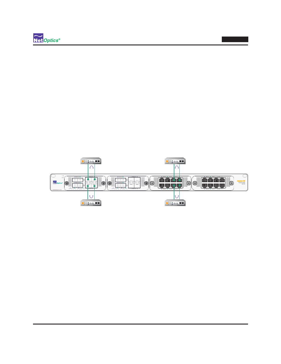
Figure 16: IPS connections (four shown out of eight possible)
Configuring the Bypass Switches
With its default factory settings, the bypass switches plug and play with no configuration needed. See the following
chapter for information about the parameters that can be changed to tune the iBypass HD for your environment.
Check the Installation
You have connected the iBypass HD to the network, IPSs, and power. To verify that it is operating correctly, check the
status of the following:
• Check that at least one power LED is illuminated.
• Check the link status LEDs located on the front panel to verify that the links are connected.
• Verify that traffic is flowing through the in-line connections and attached IPS devices.