Ibypass hd management the ibypass hd front panel, Ibypass hd management, The ibypass hd front panel – Net Optics iBypass HD User Manual
Page 11
7
iBypass HD
iBypass HD Management
The iBypass HD is configured and managed using a command-line interface (CLI) that will be familiar to most network
administrators. GUI-based Indigo management tools will be available soon.
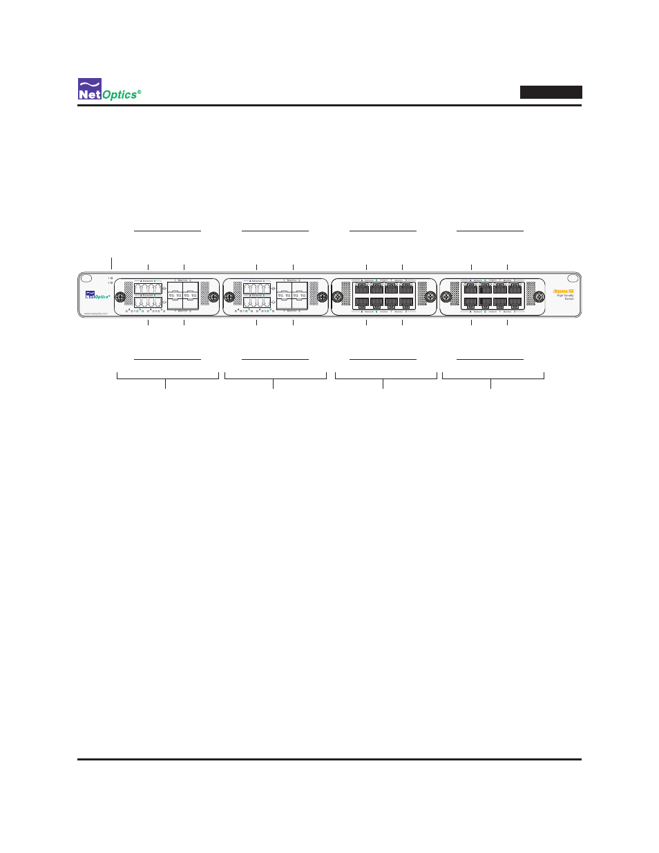
The iBypass HD Front Panel
The features of the iBypass HD front panel are shown in the following diagram.
DBM 1
(SX Fiber DBM)
Power LEDs
DBM 2
(LX Fiber DBM)
DBM 3
(10/100/1000Copper DBM)
DBM 4
(10/100/1000 Copper DBM)
Network
Ports
(LC)
Network
Ports
(LC)
Monitor
Ports
(SFP)
Monitor
Ports
(SFP)
Network
Ports
(LC)
Network
Ports
(LC)
Monitor
Ports
(SFP)
Monitor
Ports
(SFP)
Network
Ports
(RJ45)
Network
Ports
(RJ45)
Monitor
Ports
(RJ45)
Monitor
Ports
(RJ45)
Network
Ports
(RJ45)
Network
Ports
(RJ45)
Monitor
Ports
(RJ45)
Monitor
Ports
(RJ45)
Switch 1 Switch 3 Switch 5 Switch 7
Switch 2 Switch 4 Switch 6 Switch 8
Figure 5: The iBypass HD Front Panel (any mix of DBM types is allowed)
Dual Bypass Modules (DBMs)
with copper interfaces and two DBMs with fiber interfaces. Each DBM contains two complete bypass switches. The
DBMs plug into an internal backplane board which contains the processor that runs the management interfaces and
manages the switches. For purposes of identification, the DBMs are numbered 1 to 4 from left to right across the
unit. The bypass switches are numbered 1 through 8 (sw1 through sw8 in the CLI), with switches 1 and 2 in DBM 1,
switches 3 and 4 in DBM 2, switches 5 and 6 in DBM 3, and switches 7 and 8 in DBM 4. Within each DBM, the odd-
numbered (lower number) switch is the top row of ports and the even-numbered (high number) switch is bottom row of
ports.
Ports
Each DBM has eight ports, four for each bypass switch. Within each bypass switch, the network ports for the link
connections are designated A and B, and the monitor ports for the IPS connections are 1 and 2. The port order from left
to right is A, B, 1, 2. (In the CLI, the ports in bypass switch 1 are named sw1.A, sw1.B, sw1.1, and sw1.2. Although
the CLI is generally case sensitie, for the network ports lower case letters are also accepted, so the network ports can be
identified as sw1.a and sw1.b.) All ports support 1 Gigabit link speeds; 10/100/1000 copper ports are also supported.
Power LEDs
In the upper left-side corner of the front panel, two light-emitting diodes (LEDs) indicate the states of the two
redundant power supplies. The LED is illuminated if the power supply is supplying power; the LED is off when the
power supply is off.