GE Industrial Solutions QRW025 Series User Manual
Page 7
Lineage Power
7
Data Sheet
August 23, 2010
36 Vdc - 75 Vdc Input, 1.2 to 3.3 Vdc Output; 25A
QRW025 Series Power Modules; dc-dc Converters
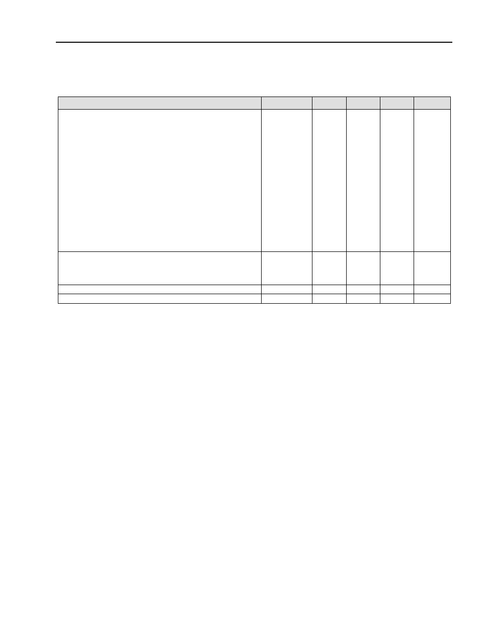
Feature Specifications
Unless otherwise indicated, specifications apply over all operating input voltage, resistive load, and temperature conditions.
See Feature Descriptions for additional information
.
* A Minimum OFF Period of 1 sec is recommended.
Parameter
Symbol
Min
Typ
Max
Unit
Remote On/Off Signal Interface*
(VI = 0 V to 75 V; open collector or equivalent compatible; signal
referenced to VI(–) terminal; see Figure 34
and Feature Descriptions.):
Preferred Logic:
Logic Low—Module On
Logic High—Module Off
Optional Logic:
Logic Low—Module Off
Logic High—Module On
Logic Low:
At Ion/off = 1.0 mA
At Von/off = 0.0 V
Logic High:
At Ion/off = 0.0 µA
Leakage Current
Turn-on Time; see Typical Start-up Curve(IO = IO max;
Vo within ±1% of steady state)
Von/off
Ion/off
Von/off
Ion/off
0
—
—
—
—
—
—
—
2
1.2
1.0
15
50
4
V
mA
V
µA
ms
Output Voltage Adjustment
(See Feature Descriptions):
Output Voltage Remote-sense Range
Output Voltage Set-point Adjustment Range (trim)
—
—
—
80
—
—
10
110
%VO,rated
%V0,nom
Output Overvoltage Protection
VO, ovsd
1.69
—
2.07
V
OvertemperaWuUe Protection (IO = IO, max)
Tref1
—
127
—
°C