Design considerations, Output capacitance, Safety considerations – GE Industrial Solutions QRW025 Series User Manual
Page 18
Lineage Power
18
Data Sheet
August 23, 2010
36 Vdc - 75 Vdc Input, 1.2 to 3.3 Vdc Output; 25A
QRW025 Series Power Modules; dc-dc Converters
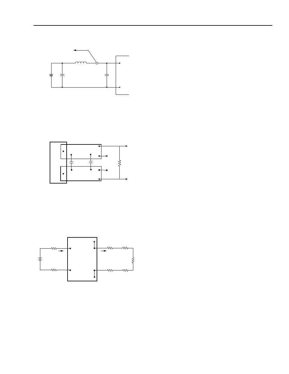
Test Configurations
Note:Measure input reflected-ripple current with a simulated
source inductance (LTEST) of 12 µH. Capacitor CS off-
sets possible battery impedance. Measure current as
shown above.
Figure 31. Input Reflected-Ripple Test Setup.
Note:Use a 1.0 µF ceramic capacitor and a 10 µF aluminum
or tantalum capacitor. Scope measurement should be
made using a BNC socket. Position the load between
51 mm and 76 mm (2 in. and 3 in.) from the module.
Figure 32. Peak-to-Peak Output Noise Measurement Test
Setup.
Note:All measurements are taken at the module terminals.
When socketing, place Kelvin connections at module
terminals to avoid measurement errors due to socket
contact resistance.
Figure 33. Output Voltage and Efficiency Measurement.
Design Considerations
Input Source Impedance
The power module should be connected to a low
ac-impedance input source. Highly inductive source imped-
ances can affect the stability of the power
module. For the test configuration in 31,
a 33 µF electrolytic capacitor (ESR < 0.7 W at 100 kHz)
mounted close to the power module helps ensure
stability of the unit. For other highly inductive source imped-
ances, consult the factory for further application guidelines.
Output Capacitance
High output current transient rate of change (high di/dt) loads
may require high values of output capacitance to supply the
instantaneous energy requirement to the load. Tp minimize
the output voltage transient drop
during this transient, low E.S.R. (equivalent series resistance)
capacitors may be required, since a high E.S.R. will produce
a correspondingly higher voltage drop during the current tran-
sient.
Output capacitance and load impedance interact with the
power module’s output voltage regulation control system and
may produce an ’unstable’ output condition for the required
values of capacitance and E.S.R.. Minimum and maximum
values of output capacitance and of the capacitor’s associ-
ated E.S.R. may be dictated, depending on the module’s con-
trol system.
The process of determining the acceptable values of capaci-
tance and E.S.R. is complex and is load-dependant. Lineage
provides Web-based tools to assist the power module end-
user in appraising and adjusting the effect of various load
conditions and output capacitances on specific power mod-
ules for various load conditions.
Safety Considerations
For safety-agency approval of the system in which the power
module is used, the power module must be installed in com-
pliance with the spacing and separation requirements of the
end-use safety agency standard, i.e., UL60950, CSA C22.2
No. 60950-00, and VDE 0805:2001-12 (IEC60950, 3rd Ed).
These converters have been evaluated to the spacing
requirements for Basic Insulation, per the above safety stan-
dards; and 1500 Vdc is applied from VI to VO to 100% of out-
going production.
For end products connected to –48 Vdc, or –60 Vdc nomianl
DC MAINS (i.e. central office dc battery plant), no further fault
testing is required.
Note:–60 V dc nominal bettery plants are not available in the
U.S. or Canada.
For all input voltages, other than DC MAINS, where the input
voltage is less than 60 Vdc, if the input meets all of the
requirements for SELV, then:
n
The output may be considered SELV. Output voltages will
V
I
(+)
V
I
(–)
CURRENT
PROBE
TO
OSCILLOSCOPE
L
TEST
12 μH
BATTERY
C
S
220 μF
ESR < 0.1 Ω
@ 20 ºC 100 kHz
COPPER STRIPS
1.0 μF
10 μF SCOPE
V
O
(+)
RESISTIVE
V
O
(-)
LOAD
CONTACT AND
SUPPLY
I
I
CONTACT
V
I
(+)
V
I
(–)
V
O
(+)
DISTRIBUTION LOSSES
RESISTANCE
I
O
LOAD
V
O
(–)
SENSE(–)
SENSE(+)
η
V
O
(+)
V
O
(-)
–
[
]
I
O
V
I
(+)
V
I
(-)
–
[
]
I
I
----------------------------------------------
⎝
⎠
⎛
⎞
100 %
Ч
=