GE Industrial Solutions QRW025 Series User Manual
Page 22
Lineage Power
22
Data Sheet
August 23, 2010
36 Vdc - 75 Vdc Input, 1.2 to 3.3 Vdc Output; 25A
QRW025 Series Power Modules; dc-dc Converters
Thermal Considerations
The power modules operate in a variety of thermal environ-
ments; however, sufficient cooling should be provided to
help ensure reliable operation of the unit. Heat-dissipating
components are mounted on the top side of the module.
Heat is removed by conduction, convection and radiation to
the surrounding environment. Proper cooling can be verified
by measuring the temperature of selected components on
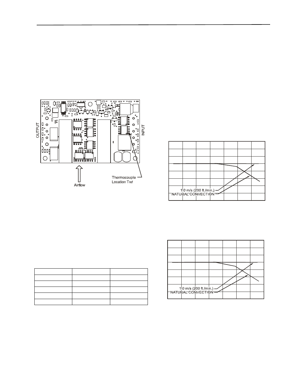
the topside of the power module (See 38). Peak temperature
(Tref) can occur at any of these positions indicated in Figure
50.
Note:Top view, pin locations are for reference only.
Figure 38. Temperature Measurement Location.
The temperature at any one of these locations should not
exceed per Table 1 to ensure reliable operation of the power
module. The output power of the module should not exceed
the rated power for the module as listed in the Ordering
Information table.
Although the maximum Tref temperature of the power mod-
ules is per Table 1, you can limit these temperatures to a
lower value for extremely high reliability.
Table 1.
Device Temperature
Heat Transfer Without Heat Sinks
Increasing airflow over the module enhances the heat trans-
fer via convection. Figures 39 through 43 shows the maxi-
mum current that can be delivered by the corresponding
module without exceeding the maximum case temperature
versus local ambient temperature (TA) for natural convection
through 2 m/s (400 ft./min.).
Note that the natural convection condition was measured at
0.05 m/s to 0.1 m/s (10ft./min. to 20 ft./min.); however, sys-
tems in which these power modules may be used typically
generate natural convection airflow rates of 0.3 m/s (60 ft./
min.) due to other heat dissipating components in the sys-
tem. The use of output power derating curve is shown in the
following example.
What is the minimum airflow necessary for a QRW025A0F
operating at VI = 48 V, an output current of 25A, and a maxi-
mum ambient temperature of 70 °C.
Solution
Given: VI = 48V
Io = 25A
TA = 70 °C
Determine airflow (v) (Use Figure 43):
v = 1m/sec. (200ft./min.)
Figure 39. Output Power Derating for QRW025A0P (Vo =
1.2V) in Transverse Orientation with No
Baseplate; Airflow direction from VIN (+) to
VIN (–); VIN = 48V.
Figure 40. Output Power Derating for QRW025A0M (Vo
= 1.5V) in Transverse Orientation with No
Baseplate; Airflow direction from VIN (+) to
VIN (–); VIN = 48V.
Output Voltage
Device
Temperature (°C)
1.2V
Tref1
114
1.5V
Tref1
111
1.8V
Tref1
117
2.5V
Tref1
117
3.3V
Tref1
117
1
40
35
30
25
20
15
10
5
0
20
30
40 50
60
70
80 90
LOCAL AMBIENT TEMPERATURE, T (°C)
A
OUTPUT CU
RRENT
, I
(A
)
O
40
35
30
25
20
15
10
5
0
20
30
40 50
60 70
80
90
LOCAL AMBIENT TEMPERATURE, T (°C)
A
OUT
P
UT CU
R
R
ENT
, I
(A
)
O