Data sheet, Layout considerations – GE Industrial Solutions JRCW016A0R Orca Series User Manual
Page 11
GE
Data Sheet
JRCW016A0R Orca Series; DC-DC Converter Power Modules
36–75 Vdc Input; 28.0Vdc Output; 16Adc Output
November 20, 2013
©2012 General Electric Company. All rights reserved.
Page 11
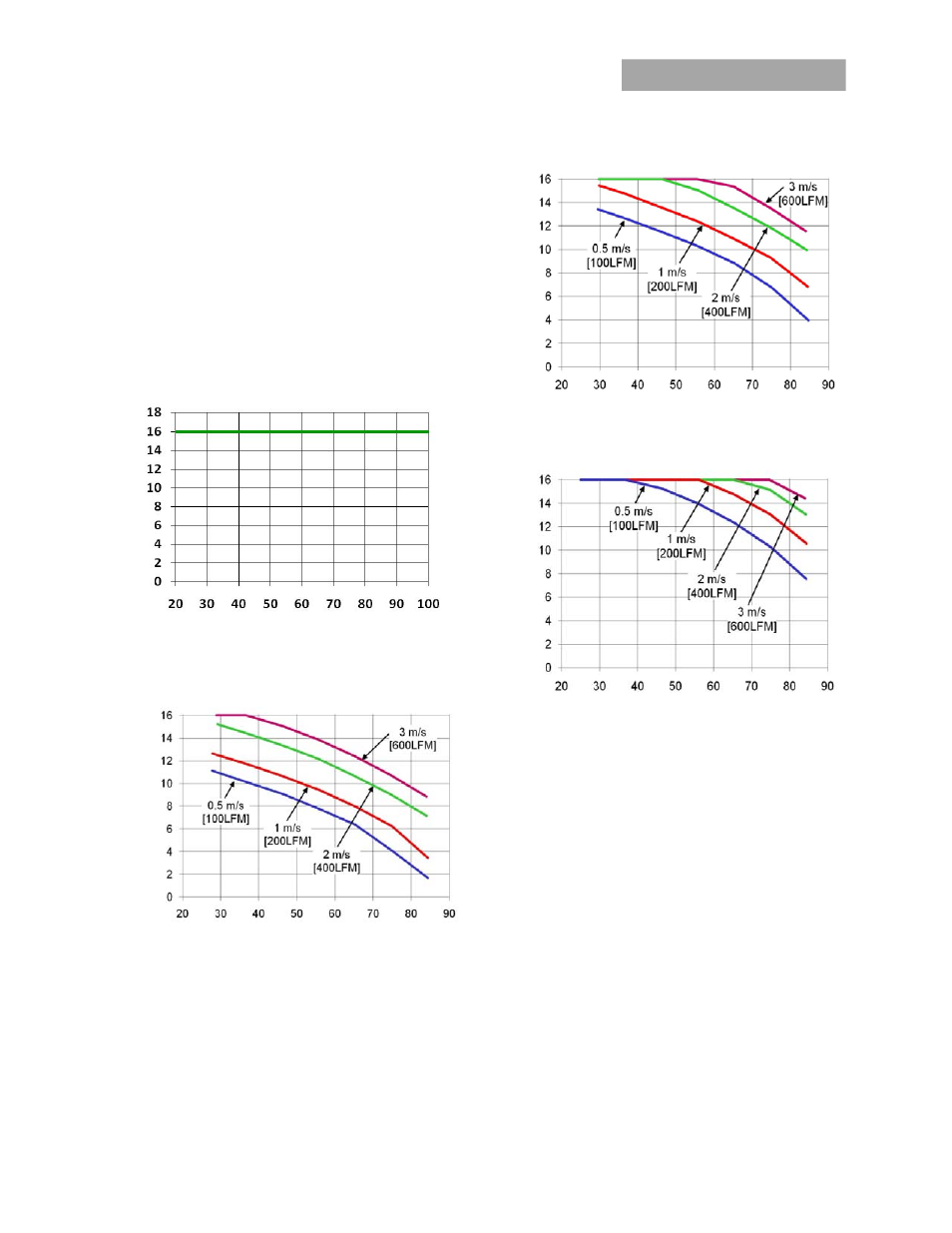
Thermal Derating
Thermal derating is presented for two different applications: 1)
Figure 18, the JRCW016A0R module is thermally coupled to a
cold plate inside a sealed clamshell chassis, without any
internal air circulation; and 2) Figure 19,20 and 21, the
JRCW016A0R module is mounted in a traditional open chassis
or cards with forced air flow. In application 1, the module is
cooled entirely by conduction of heat from the module
primarily through the top surface to a cold plate, with some
conduction through the module’s pins to the power layers in
the system board. For application 2, the module is cooled by
heat removal into a forced airflow that passes through the
interior of the module and over the top base plate and/or
attached heatsink.
Output Cu
rrent, I
O
(A
)
Cold plate (inside surface) temperature (ºC)
Figure 18. Output Power Derating for JRCW016A0R in
Conduction cooling (cold plate) applications; T
a
<70ºC
adjacent to module; V
IN
= V
IN,NOM
Output C
urrent, I
O
(A
)
Ambient
Temperature,
T
A
(
o
C)
Figure 19. Derating Output Current vs. local Ambient
temperature and Airflow, No Heatsink, Vin=48V, airflow
from Vi(-) to Vi(+).
Output C
urrent, I
O
(A
)
Ambient Temperature, T
A
(
o
C)
Figure 20. Derating Output Current vs. local Ambient
temperature and Airflow, 0.5” Heatsink, Vin=48V, airflow
from Vi(-) to Vi(+).
Output Curr
en
t,
I
O
(A)
Ambient Temperature, T
A
(
o
C)
Figure 21. Derating Output Current vs. local Ambient
temperature and Airflow, 1.0” Heatsink, Vin=48V, airflow
from Vi(-) to Vi(+).
Layout Considerations
The JRCW016A0R power module series are constructed using
a single PWB with integral base plate; as such, component
clearance between the bottom of the power module and the
mounting (Host) board is limited. Avoid placing copper areas
on the outer layer directly underneath the power module.
Post Solder Cleaning and Drying Considerations
Post solder cleaning is usually the final circuit-board assembly
process prior to electrical board testing. The result of
inadequate cleaning and drying can affect both the reliability
of a power module and the testability of the finished
circuit-board assembly. For guidance on appropriate
soldering, cleaning and drying procedures, refer to GE Board
Mounted Power Modules: Soldering and Cleaning Application
Note.