Data sheet, Thermal considerations – GE Industrial Solutions JRCW016A0R Orca Series User Manual
Page 10
GE
Data Sheet
JRCW016A0R Orca Series; DC-DC Converter Power Modules
36–75 Vdc Input; 28.0Vdc Output; 16Adc Output
November 20, 2013
©2012 General Electric Company. All rights reserved.
Page 10
Figure 16. Circuit diagram showing connection of R
TUNE
and
C
TUNE
to tune the control loop of the module.
Table 1 shows the recommended values of R
TUNE
and C
TUNE
for
different values of ceramic output capacitors up to 8000 F
that might be needed for an
application to meet output ripple and noise requirements.
Table 1. General recommended values of of R
TUNE
and C
TUNE
for V
out
=28V and various external ceramic capacitor
combinations.
C
out
(µF)
1100
2200
4400
6600
8800
ESR (mΩ)
60
30
15
10
7.5
R
TUNE
12k 4.7k 1.8k 820 390
C
TUNE
220nF 220nF 220nF 220nF 220nF
Please contact your GE technical representative to obtain
more details of this feature as well as for guidelines on how to
select the right value of external R-C to tune the module for
best transient performance and stable operation for other
output capacitance values.
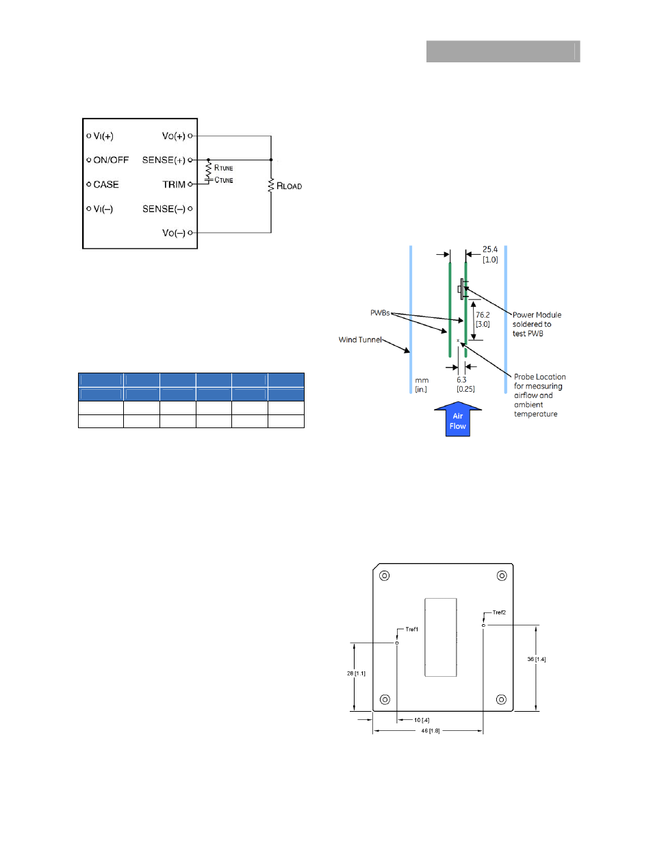
Over Temperature Protection
The JRCW016A0R module provides a non-latching over
temperature protection. A temperature sensor monitors the
operating temperature of the converter. If the reference
temperature, T
REF 1
, (see Figure 17) exceeds a threshold of 115
ºC (typical), the converter will shut down and disable the
output. When the base plate temperature has decreased by
approximately 20 ºC the converter will automatically restart.
The module can be restarted by cycling the dc input power for
at least one second or by toggling the remote on/off signal for
at least one second.
Thermal Considerations
The power modules operate in a variety of thermal
environments; however, sufficient cooling should be provided
to help ensure reliable operation of the unit. Heat-dissipating
components inside the unit are thermally coupled to the case.
Heat is removed by conduction, convection, and radiation to
the surrounding environment. Proper cooling can be verified
by measuring the case temperature. Peak temperature (T
REF
)
occurs at the position indicated in Figure 17.
Considerations include ambient temperature, airflow, module
power dissipation, and the need for increased reliability. A
reduction in the operating temperature of the module will
result in an increase in reliability.
The thermal data presented here is based on physical
measurements taken in a wind tunnel, using automated
thermo-couple instrumentation to monitor key component
temperatures: FETs, diodes, control ICs, magnetic cores,
ceramic capacitors, opto-isolators, and module pwb
conductors, while controlling the ambient airflow rate and
temperature. For a given airflow and ambient temperature,
the module output power is increased, until one (or more) of
the components reaches its maximum derated operating
temperature, as defined in IPC-9592. This procedure is then
repeated for a different airflow or ambient temperature until a
family of module output derating curves is obtained.
Heat-dissipating components inside the unit are thermally
coupled to the case. Heat is removed by conduction,
convection, and radiation to the surrounding environment.
For reliable operation this temperature should not
exceed 100ºC at either T
REF 1
or T
REF 2
for applications using
forced convection airflow or cold plate applications. The
output power of the module should not exceed the rated
power for the module as listed in the ordering Information
table. Although the maximum T
REF
temperature of the power
modules is discussed above, you can limit this temperature to
a lower value for extremely high reliability.
Figure 17.
Case (T
REF
) Temperature Measurement Location
(top view).