3 interior view, 4 cautions and warnings, Nterior – GE Industrial Solutions EPM4500 Submeter User Manual
Page 7: Autions, Arnings
CHAPTER 1: OVERVIEW
APPLICATIONS
EPM 4500 SUB METER – INSTRUCTION MANUAL
1–3
1.2.3
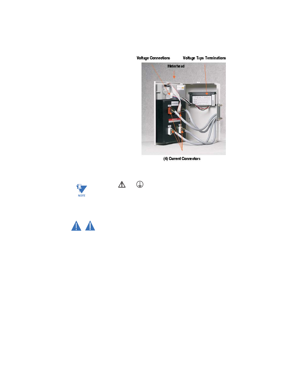
Interior View
The interior of the EPM4500 is shown below.
FIGURE 1–2: Interior View of the EPM4
500
Note
Where the
and
symbols are seen on the EPM4500 meter, the manual must be
consulted to determine the nature of any potential hazard and/or actions to be taken.
1.2.4
Cautions and Warnings
• Do not install if the device is damaged. Inspect the housing for obvious defects
such as cracks in the housing.
• If the device is installed or used in a manner not specified by accompanying
documents, the protection of the device may be impaired.
• If the device functions abnormally, proceed with caution. The protection of the
device may be impaired.
• Do not install the meter around combustible gas or gas vapor.
• Do not install the meter in an electrical service with current or voltage outside of
the specified limit of the device.
• Do not operate the meter with the cover removed.
• To avoid electric shock, disconnect mains before replacing fuses!
• See instructions for connection diagram.
• Risk of electric shock. Beware of working around this meter when the voltage is
live.
• For continued protection against fire, replace only with fuses of specified voltage
and current rating.
709711A1.CDR
WARNING
CAUTION