Feature descriptions – GE Industrial Solutions KW010-015-020-025 (Sixteenth-Brick) User Manual
Page 14
Data Sheet
October 7, 2013
KW010/015/020/025 Series Power Modules:
36
– 75Vdc Input; 1.2 to 5.0Vdc Output; 10 to 25A Output current
LINEAGE
POWER
14
Feature Descriptions
(continued)
current-limiting circuitry and can endure current
limiting continuously. At the point of current-limit
inception, the unit enters hiccup mode. If the unit is
not configured with auto
–restart, then it will latch off
following the over current condition. The module can
be restarted by cycling the dc input power for at least
one second or by toggling the remote on/off signal for
at least one second. If the unit is configured with the
auto-restart option (4), it will remain in the hiccup
mode as long as the overcurrent condition exists; it
operates normally, once the output current is brought
back into its specified range. The average output
current during hiccup is 10% I
O, max
.
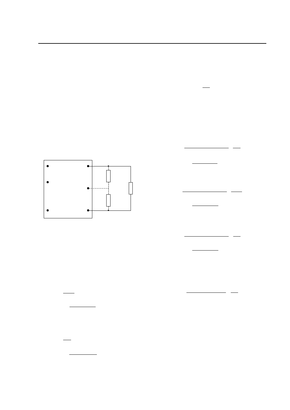
Output Voltage Programming
Trimming allows the output voltage set point to be
increased or decreased, this is accomplished by
connecting an external resistor between the TRIM pin
and either the V
O
(+) pin or the V
O
(-) pin.
V
O
(+)
V
O
TRIM
V
O
(-)
R
trim-down
LOAD
V
IN
(+)
ON/OFF
V
IN
(-)
R
trim-up
Figure 42. Circuit Configuration to Trim Output
Voltage.
Connecting an external resistor (R
trim-down
) between
the TRIM pin and the Vo(-) (or Sense(-)) pin
decreases the output voltage set point. To maintain
set point accuracy, the trim resistor tolerance should
be ±1.0%.
The following equation determines the required
external resistor value to obtain a percentage output
voltage change of Δ%.
For output voltage: 1.2V (SMT versions only):
k
R
down
trim
65
.
7
%
5
.
255
Where
100
2
.
1
2
.
1
%
V
V
V
desired
For output voltage: 1.2V (Through-Hole versions
only) and all 1.5V to 12V:
k
R
down
trim
22
.
10
%
511
Where
100
%
,
,
set
o
desired
set
o
V
V
V
For example, to trim-down the output voltage of 2.5V
module (KW020A0G/G1) by 8% to 2.3V, Rtrim-down
is calculated as follows:
8
%
k
R
down
trim
22
.
10
8
511
k
R
down
trim
655
.
53
Connecting an external resistor (R
trim-up
) between the
TRIM pin and the V
O
(+) (or Sense (+)) pin increases
the output voltage set point. The following equations
determine the required external resistor value to
obtain a percentage output voltage c
hange of Δ%:
For output voltage: all 1.5V to 12V:
k
V
R
set
o
up
trim
22
.
10
%
511
%
225
.
1
%)
100
(
11
.
5
,
Where
100
%
,
,
set
o
set
o
desired
V
V
V
For output voltage: 1.2V (SMT versions only):
k
V
R
up
trim
665
.
7
%
5
.
255
%
225
.
1
%)
100
(
2
.
1
11
.
5
Where
100
2
.
1
2
.
1
%
V
V
V
desired
For output voltage: 1.2V (Through-Hole versions
only):
k
V
R
up
trim
22
.
10
%
511
%
6
.
0
%)
100
(
2
.
1
11
.
5
Where
100
2
.
1
2
.
1
%
V
V
V
desired
For example, to trim-up the output voltage of 1.2V
through hole module (KW025A0P/P1) by 5% to
1.26V, R
trim-up
is calculated is as follows:
5
%
k
R
up
trim
22
.
10
5
511
5
6
.
0
)
5
100
(
2
.
1
11
.
5
k
R
up
trim
2
.
102
The voltage between the Vo(+) and Vo(
–) terminals
must not exceed the minimum output overvoltage
protection value shown in the Feature Specifications
table. This limit includes any increase in voltage due
to remote-sense compensation and output voltage
set-point adjustment trim.
Although the output voltage can be increased by both
the remote sense and by the trim, the maximum
increase for the output voltage is not the sum of both.