6 connectivity, 1 customer interface im0005, Customer interface im0005 – GE Industrial Solutions IEMi User Manual
Page 23: X1 j2 j3, Jp3 x2 a b
6 CONNECTIVITY
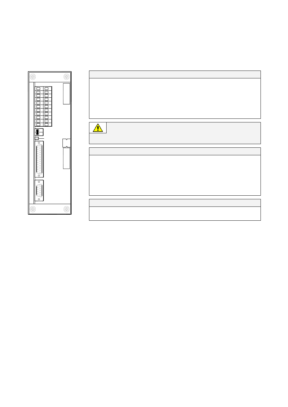
6.1 CUSTOMER INTERFACE IM0005
J2 (sub D-female 25p) – Output signals on voltage free contacts
J2 / 1, 2, 3
NO, C, NC
Mains Failure
(def. Parameter RL=1)
J2 / 4, 5, 6
NO, C, NC
Load on Inverter
(def. Parameter RL=3)
J2 / 7, 8, 9
NO, C, NC
Stop Operation
(def. Parameter RL=5)
J2 / 14, 15, 16
NO, C, NC
Load on Mains
(def. Parameter RL=2)
J2 / 17, 18, 19
NO, C, NC
General Alarm
(def. Parameter RL=4)
J2 / 20, 21, 22
NO, C, NC
Acoustic Alarm
(def. Parameter RL=6)
Signals on terminals X1 and on connector J2 are in parallel and therefore not
separated galvanically from each other.
The programmable signals on X1 and J2 will be disabled with Q1 open, with the
exception of the signals for “16 - Manual Bypass ON” and “26 - EPO”.
X1 terminals – Output signals on voltage free contacts
X1 / 1, 2, 3
NO, C, NC
Mains Failure
(def. Parameter RL=1)
X1 / 4, 5, 6
NO, C, NC
Load on Inverter
(def. Parameter RL=3)
X1 / 7, 8, 9
NO, C, NC
Stop Operation
(def. Parameter RL=5)
X1 / 12, 13, 14
NO, C, NC
Load on Mains
(def. Parameter RL=2)
X1 / 15, 16, 17
NO, C, NC
General Alarm
(def. Parameter RL=4)
X1 / 18, 19, 20
NO, C, NC
Acoustic Alarm
(def. Parameter RL=6)
Input contacts
X1 / 10, 21 or J2 / 10, 23
NO Programmable
1
12
13
2
14
3
15
4
16
5
17
6
18
7
19
8
20
9
21
10
22
11
14
1
9
1
X1
J2
J3
SGSE_160-200_S1_Customer interface_02
J2
2
1
JP3
X2
A
B
J3
X1 / 11, 22 or J2 / 11, 24
NO
Programmable / Generator ON
Fig. 7.1-1 Customer interface IM 0005
On terminals X1 or J2 connector, the output signals can be associated to a specific function.
This selection can be performed from the display by QUALIFIED AND TRAINED PERSONNEL (password
required).
With reference to IEMi Operation Mode, the following function is available:
27- eBoost/IEMi mode.
This signal indicates when IEMi Operation Mode is enabled and active.
Some UPS functions can be activated when an external Normally Open contact is closed on:
X1-10, 21 / J2-10, 23 or X1-11, 22 / J2- 11, 24
The specific function can be selected from the display by QUALIFIED AND TRAINED PERSONNEL
(password required).
With reference to IEMi Operation Mode, the following function is available:
8 – eBoost/IEMi control.
When active, this function will deactivate IEMi Operation Mode.
Modifications reserved
Page 23/24
OPM_OPT_IEM_iXX_XXX_XGB_V010.doc
User Manual IEMi - Intelligent Energy Management integrated