Feature specifications – GE Industrial Solutions JRW017-040-060-065-070 Series User Manual
Page 5
Data Sheet
June 14, 2010
JRW017-070 Series Power Modules DC-DC Converters
36-75Vdc Input; 1.2Vdc to 12Vdc Output
LINEAGE
POWER
5
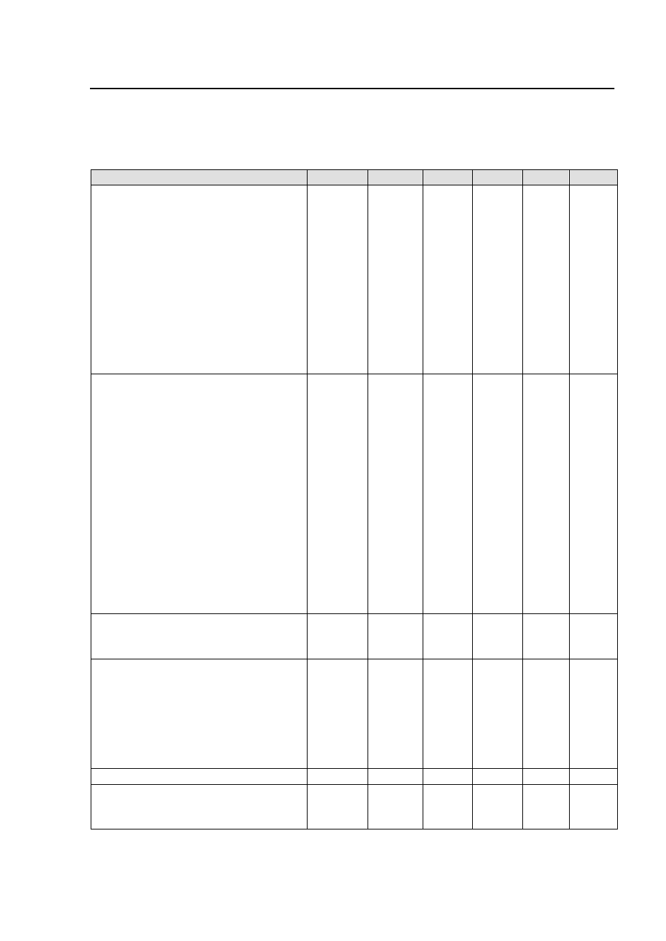
Feature Specifications
Unless otherwise indicated, specifications apply over all operating input voltage, resistive load, and temperature
conditions. See Feature Descriptions for additional information.
Parameter
Device
Symbol
Min
Typ
Max
Unit
Remote On/Off Signal interface
(V
I
= V
I
,min to V
I
, max; Open collector or equivalent
Compatible, signal referenced to V
I
(-) terminal)
Negative Logic: device code suffix “1”
Logic Low=module On, Logic High=Module Off
Positive Logic: No device code suffix required
Logic Low=module Off, Logic High=Module On
Logic Low Specification
Remote On/Off Current-Logic Low
All
I
on/Off
―
0.15
1.0
mA
On/Off Voltage:
Logic Low
All
V
on/Off
0.0
―
1.2
V
Logic High (Typ=Open Collector)
All
V
on/Off
―
―
15
V
Logic High maximum allowable leakage current
All
I
on/Off
―
―
50
µA
Turn-On Delay and Rise Times
(I
O
=I
O, max
)
T
delay
= Time until V
O
= 10% of V
O,set
from either
P
T
delay
―
2
―
msec
application of Vin with Remote On/Off set to On or
M
―
2
―
msec
operation of Remote On/Off from Off to On with Vin
Y
―
2
―
msec
already applied for at least one second.
G
―
5
―
msec
F
―
2
―
msec
A
―
2.5
―
msec
B
―
2.5
―
msec
T
rise
= time for V
O
to rise from 10% of V
O,set
to 90%
of V
O,set
.
P
T
rise
―
1
―
msec
M
―
1
―
msec
Y
―
1
―
msec
G
―
3
―
msec
F
―
1
―
msec
A
―
1
―
msec
B
―
1
―
msec
Output voltage adjustment range (TRIM)
Output Voltage Remote sense range
V
sense
―
―
10
% V
O, nom
Output Voltage Set-point Adjustment range
80
―
110
% V
O, nom
Output Over voltage protection
P
V
Oovsd
1.4
―
1.6
Vdc
M
1.8
―
2.2
Vdc
Y
2.3
―
2.6
Vdc
G
2.9
―
3.4
Vdc
F
3.8
―
4.6
Vdc
A
5.7
―
6.5
Vdc
B
14
―
16
Vdc
Over temperature Protection
All
T
ref
127
°C
Input Undervoltage Lockout
V
in, OVLO
Turn-on Threshold
34.5
36
V
Turn-off Threshold
30
32.5
V