Electrical specifications (continued), Isolation specifications, General specifications – GE Industrial Solutions JRW017-040-060-065-070 Series User Manual
Page 4: Electrical specifications
Data Sheet
June 14, 2010
JRW017-070 Series Power Modules DC-DC Converters
36-75Vdc Input; 1.2Vdc to 12Vdc Output
LINEAGE
POWER
4
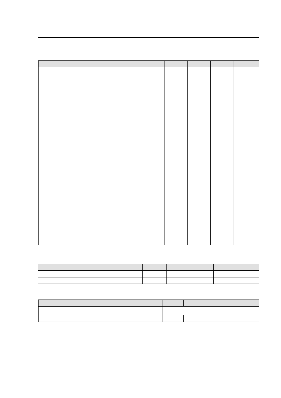
Electrical Specifications
(continued)
Parameter
Device
Symbol
Min
Typ
Max
Unit
Efficiency
P
η
84
%
(V
IN
=V
IN,nom
, I
O
=I
O, max
, V
O
= V
O,set
T
A
=25°C)
M
86
%
Y
87
%
G
90
%
F
91
%
A
92
%
B
92
%
Switching Frequency
f
sw
300
kHz
Dynamic Load Response
(
∆Io/∆t=1A/10µs; V
in
=V
in
,nom; T
A
=25°C;
Tested with a 10 μF aluminum and a 1.0
μF tantalum capacitor across the load.)
Load Change from Io= 50% to 75% of
Io,max:
Peak Deviation
P,M,Y,G
V
pk
6
%V
O, set
Settling Time (Vo<10% peak deviation)
t
s
300
µs
F,A
V
pk
4
%V
O, set
t
s
300
µs
B
V
pk
3
%V
O, set
t
s
500
µs
Load Change from Io= 75% to 50% of
Io,max:
Peak Deviation
P,M,Y,G
V
pk
6
%V
O, set
Settling Time (Vo<10% peak deviation)
t
s
300
µs
F,A
V
pk
4
%V
O, set
t
s
300
µs
B
V
pk
3
%V
O, set
t
s
500
µs
Isolation Specifications
Parameter
Symbol
Min
Typ
Max
Unit
Isolation Capacitance
C
ISO
2700
pF
Isolation Resistance
R
ISO
10
MΩ
General Specifications
Parameter
Min
Typ
Max
Unit
Calculated MTBF (I
O
= 80% of I
O, max
, T
A
=40°C,
airflow=1m/s
(400LFM)
1,363,000
Hours
Weight
60.3 (2.1)
g (oz.)