Electrical specifications (continued), Electrical specifications – GE Industrial Solutions JRW017-040-060-065-070 Series User Manual
Page 3
Data Sheet
June 14, 2010
JRW017-070 Series Power Modules DC-DC Converters
36-75Vdc Input; 1.2Vdc to 12Vdc Output
LINEAGE
POWER
3
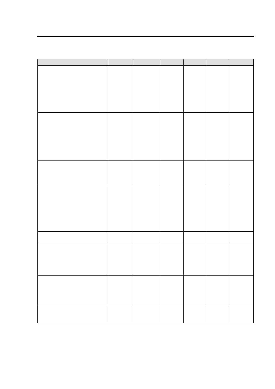
Electrical Specifications
(continued)
Parameter
Device
Symbol
Min
Typ
Max
Unit
Output Voltage Set-point
P
V
O, set
1.18
1.20
1.22
Vdc
(V
IN
=V
IN,nom
, I
O
=I
O, max
, T
ref
=25°C)
M
1.47
1.50
1.52
Vdc
Y
1.77
1.80
1.83
Vdc
G
2.47
2.50
2.53
Vdc
F
3.24
3.30
3.36
Vdc
A
4.95
5.0
5.05
Vdc
B
11.76
12.0
12.24
Vdc
Output Voltage
P
V
O
1.16
1.24
Vdc
(Over all operating input voltage,
resistive load, and temperature
M
1.45
1.55
Vdc
conditions until end of life)
Y
1.75
1.85
Vdc
G
2.42
2.58
Vdc
F
3.20
3.40
Vdc
A
4.85
5.15
Vdc
B
11.64
12.36
Vdc
Output Regulation
Line (V
IN
= V
IN, min
to V
IN, max
)
0.05
0.2
% V
O, nom
Load (I
O
= I
O, min
to I
O, max
)
0.05
0.2
% V
O, nom
Temperature (T
A
=-40ºC to +85ºC)
15
50
mV
Output Ripple and Noise on nominal
output
(V
IN
=V
IN, nom
and I
O
= I
O, min
to I
O, max
,
C
out
= 1
μF ceramic // 10μF Tantalum
capacitor)
RMS (5Hz to 20MHz bandwidth)
40
mV
rms
Peak-to-Peak (5Hz to 20MHz
bandwidth)
100
mV
pk-pk
External Capacitance
P,M,Y,G,F
C
Out,ext
30,000
μF
A,B
C
Out,ext
10,000
μF
Output Current
P,M
I
o
0
70
A
G,Y
0
65
A
F
0
60
A
A
0
40
A
B
0
17
A
Output Current Limit Inception
P,M
I
O, cli
80
A
G,Y
73
A
F
64
A
A
50
A
B
21
A
Output Short-Circuit Current
All
Latched-
off
V
O
≤ 250 mV @ 25
o
C