Heat transfer via convection, Thermal considerations – GE Industrial Solutions JRW017-040-060-065-070 Series User Manual
Page 18
Data Sheet
June 14, 2010
JRW017-070 Series Power Modules DC-DC Converters
36-75Vdc Input; 1.2Vdc to 12Vdc Output
LINEAGE
POWER
18
Thermal Considerations
The power modules operate in a variety of thermal
environments; however, sufficient cooling should be
provided to help ensure reliable operation.
Considerations include ambient temperature, airflow,
module power dissipation, and the need for increased
reliability. A reduction in the operating temperature of
the module will result in an increase in reliability. The
thermal data presented here is based on physical
measurements taken in a wind tunnel.
Heat-dissipating components are mounted on the
topside of the module. Heat is removed by
conduction, convection and radiation to the
surrounding environment. Proper cooling can be
verified by measuring the thermal reference
temperature (T
ref
). The peak temperature (T
ref
)
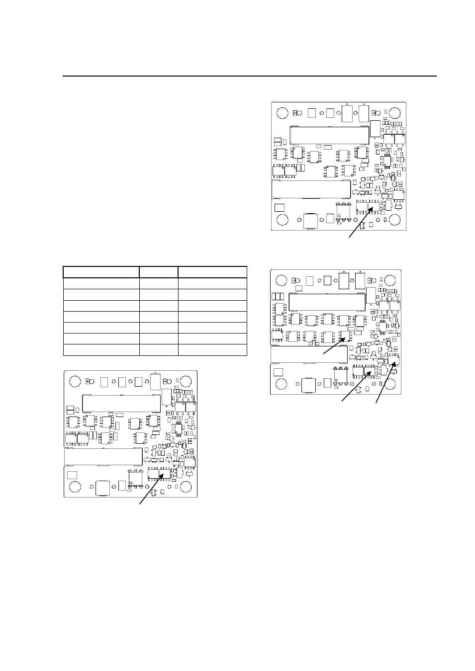
occurs at the position indicated in Figures 50 - 52.
The temperature at any one of these locations should
not exceed per below table to ensure reliable
operation of the power module.
Figure 50. T
ref
Temperature Measurement
Location for Vo= 12V.
Please refer to the Application Note “Thermal
Characterization Process For Open-Frame Board-
Mounted Power Modules” for a detailed discussion of
thermal aspects including maximum device
temperatures.
Figure 51. T
ref
Temperature Measurement
Location for Vo= 5V.
Figure 52. T
ref
Temperature Measurement
Locations for Vo= 3.3V – 1.2V.
The output power of the module should not exceed
the rated power for the module as listed in the
Ordering Information table.
Although the maximum T
ref
temperature of the power
modules is approximately 117 °C, you can limit this
temperature to a lower value for extremely high
reliability.
Heat Transfer via Convection
Increased airflow over the module enhances the heat
transfer via convection. Following derating figures
shows the maximum output current that can be
delivered by each module in the respective orientation
without exceeding the maximum T
ref
temperature
versus local ambient temperature (T
A
) for natural
convection through 2m/s (400 ft./min).
Model
Device
Temperature( ºC)
JRW070A0P (1.2V)
T
ref3
117
JRW070A0M (1.5V)
T
ref2
/ T
ref3
115/118
JRW065A0Y (1.8V)
T
ref3
115
JRW065A0G (2.5V)
T
ref2
/ T
ref3
117/118
JRW060A0F (3.3V)
T
ref1
/ T
ref2
117/118
JRW040A0A (5V)
T
ref1
117
JRW017A0B (12V)
T
ref1
117
T
ref1
T
ref3
T
ref1
T
ref2
T
ref1