Characteristic curves, Electrical specifications – GE Industrial Solutions LC-LW015-Series User Manual
Page 7
Data Sheet
March 27, 2008
Lineage Power
7
18 Vdc to 36 Vdc or 36 Vdc to 75 Vdc Inputs, 10 W and 15 W
LC/LW010- and LC/LW015-Series Power Modules:
Electrical Specifications
(continued)
Output Voltage Set-point Adjustment Range
(optional: single outputs only)
A, B, F
C
D
—
—
—
90
90
90
—
—
—
110
100
125
%V
O, nom
%V
O, nom
%V
O, nom
Output Overvoltage Clamp
(V
O
,
clamp
may be set higher on units with out-
put voltage set-point adjustment option.)
D
F
A
B
C
AJ
BK
CL
V
O, clamp
V
O, clamp
V
O, clamp
V
O, clamp
V
O, clamp
V
O1, clamp
V
O2, clamp
V
O1, clamp
V
O2, clamp
V
O1, clamp
V
O2, clamp
2.60
3.7
5.6
13.2
16.5
5.6
–5.6
13.2
–13.2
16.5
–16.5
—
—
—
—
—
—
—
—
—
—
—
4.0
5.7
7.0
16.0
21.0
7.0
–7.0
18.0
–18.0
21.0
–21.0
V
V
V
V
V
V
V
V
V
V
V
Undervoltage Lockout
LCxxx
LWxxx
V
uvlo
V
uvlo
11
20
14
27
—
—
V
V
Table 5. Feature Specifications (continued)
Parameter
Device Code
or Suffix
Symbol
Min
Typ
Max
Unit
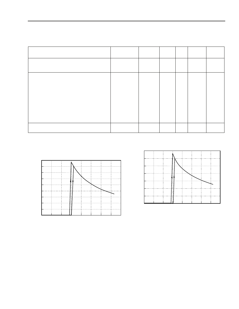
Characteristic Curves
8-1785(C)
Figure 1. LC010 Input Current vs. Input Voltage at
I
O
= I
O
,
max
and T
C
= 25 °C
8-1786(C)
Figure 2. LC015 Input Current vs. Input Voltage at
I
O
= I
O
,
max
and T
C
= 25 °C
5
10
15
25
20
30
0.0
0.6
INPUT VOLTAGE, V
I
(V)
0.4
0.3
0.5
35
0.8
40
0
0.7
0.2
0.1
0.9
INPUT CURRENT
,
I
I
(A)
0.4
0.0
0.8
1.2
1.4
0.2
0.6
1.0
5
10
15
35
20
40
0
30
25
INPUT VOLTAGE, V
I
(V)
INPUT CURRENT
,
I
I
(A)