Test configurations, Figure 33. input reflected-ripple test setup, S 35 and – GE Industrial Solutions LC-LW015-Series User Manual
Page 14: S 34, D 37.)
14
14
Lineage Power
Data Sheet
March 27, 2008
18 Vdc to 36 Vdc or 36 Vdc to 75 Vdc Inputs, 10 W and 15 W
LC/LW010- and LC/LW015-Series Power Modules:
Test Configurations
8-203(C)
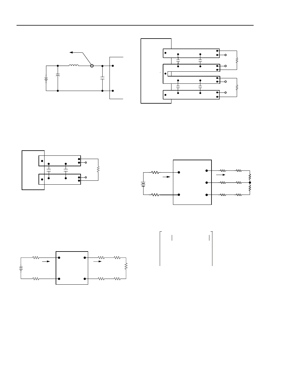
Note: Input reflected-ripple current is measured with a simulated
source impedance of 12 µH. Capacitor Cs offsets possible
battery impedance. Current is measured at the input of the
module.
Figure 33. Input Reflected-Ripple Test Setup
8-513(C).g
Note: Use two 0.47 µF ceramic capacitors. Scope measurement
should be made using a BNC socket. Position the load
between 50 mm and 75 mm (2 in. and 3 in.) from the module.
Figure 34. Peak-to-Peak Output Noise
Measurement Test Setup for Single
Outputs
8-204(C)
Note: All measurements are taken at the module terminals. When
socketing, place Kelvin connections at module terminals to
avoid measurement errors due to socket contact resistance.
Figure 35. Output Voltage and Efficiency
Measurement Test Setup for Single
Outputs
8-808(C).d
Note: Use four 0.47 µF ceramic capacitors. Scope measurement
should be made using a BNC socket. Position the load
between 50 mm and 75 mm (2 in. and 3 in.) from the module.
Figure 36. Peak-to-Peak Output Noise
Measurement Test Setup for Dual
Outputs
8-863(C).a
Note: All measurements are taken at the module terminals. When
socketing, place Kelvin connections at module terminals to
avoid measurement errors due to socket contact resistance.
Figure 37. Output Voltage and Efficiency
Measurement Test Setup for Dual
Outputs
TO OSCILLOSCOPE
12 µH
C
S
220 µF
IMPEDANCE < 0.1
Ω
@ 20 ˚C, 100 kHz
V
I
(+)
V
I
(-)
BATTERY
33 µF
CURRENT
PROBE
L
TEST
V
O
(+)
V
O
(–)
0.47 µF
RESISTIVE
LOAD
SCOPE
COPPER STRIP
0.47 µF
V
I
(+)
V
I
(-)
V
O
(+)
V
O
(-)
I
I
I
O
SUPPLY
CONTACT RESISTANCE
CONTACT AND
DISTRIBUTION LOSSES
LOAD
η
V
O
(+) V
O
(–)
–
[
]I
O
V
I
(+)
V
I
(–)
–
[
]I
I
------------------------------------------------
⎝
⎠
⎛
⎞ 100
×
=
V
O1
(+ )
V
O2
(-)
0.47 µF
0.47 µF
SCOPE
COPPER STRIP
SCOPE
COM
R
LOAD1
R
LOAD2
0.47 µF
0.47 µF
V
I
(+)
I
I
I
O
SUPPLY
CONTACT
RESISTANCE
CONTACT AND
DISTRIBUTION LOSSES
LOAD
V
I
(-)
V
O1
V
O2
COM
LOAD
η
V
OJ
COM
–
[
]
I
OJ
J
1
=
2
∑
V
I
+
( )
V
I
–
( )
–
[
]
I
I
---------------------------------------------------
x 100
=