3 control bus cable location, Control bus cable location, Next parallel unit – GE Industrial Solutions SG Series 50 & 80 kVA Installation Guide User Manual
Page 32: Access to the control bus connection
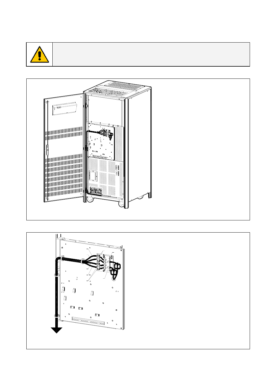
3.9.3 Control bus cable location
WARNING !
This operation must be performed by trained personnel before the initial start-up.
ENSURE THAT THE UPS INSTALLATION IS COMPLETELY POWERED DOWN.
SGT
5000
_0
50
-0
80_R
PA c
on
tr
ol
b
us
c
abl
e_01b
Access to the control bus
connection.
Q1
OF
F
ON
Q2
ON
OF
F
The control bus connection
between parallel units must be
made on the front of the
electronic module fitted behind
the front doors.
Fig. 3.9.3-1 View electronic module on intermediate unit
SGT
5
0
00_1
00
-1
50
_RPA con
tr
o
l b
u
s
cable_
02US
JB2
JB1
JA2
JA1
A
A
JA
JB
Next parallel unit
Fig. 3.9.3-2 Front view electronic module on intermediate unit
Control bus cables connection.
• Plug the cables JA (1/2/3/4/5/6/7) and
JB (1/2/3/4/5/6/7) onto the RJ
connectors JA and JB located on
parallel bus PCB “P34 – Bus Interface”
(going to “P13 – RPA Board” J52(A) and
J62(B).
• Fix both cables JA (1/2/3/4/5/6/7) and
JB (1/2/3/4/5/6/7) to parallel bus
socket connecting the cable shield to
ground by means the cable clamps
“A“.
Modifications reserved
Page 32/38
OPM_SGS_ISG_50K_80K_0US_V040.doc
Installation Guide SG Series 50 & 80 kVA