Openings for input and output cable connections, See fig. 3.4.1-5 – GE Industrial Solutions SG Series 50 & 80 kVA Installation Guide User Manual
Page 13
Openings for input and output cable connections
SG
T5
00
0_
05
0-0
80
_U
PS
vie
w t
op
_01
US
31.
50"
800
mm
13.
86"
352
mm
1.18"
30mm
30m
m
1.1
8"
57mm
2.25"
31.50"
800mm
Utility input
Output Load
Battery
Fig. 3.4.1-2 Opening on top of the cabinet for input and output cables
SG Series openings are
provided on the top and the
bottom of the UPS for the
connection of input and
output cables.
Pay attention to the position
of these openings, when
choosing the placement of
the UPS.
These openings are covered
with a protective plate.
SG
T5
00
0_0
50-
08
0_U
PS
vie
w b
ott
om
_02
US
Utility input
Output Load
31.50"
800mm
6.1
0"
155
mm
120mm
4.73"
32mm
1.26"
7.7
6"
197
mm
31.
50"
800
mm
Fig. 3.4.1-3 Opening on the bottom of the cabinet for input and output cables
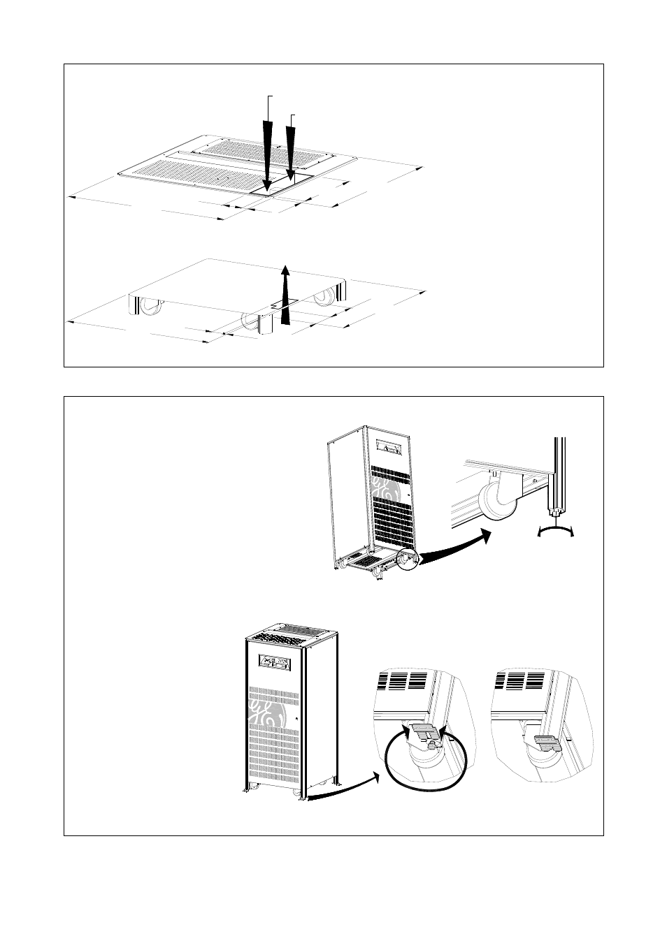
Positioning of the UPS cabinet
SG Series is equipped with wheels for easy
placement of the UPS.
To make the UPS movable on wheels, the bolts
on each leg of the cabinet have to be turned
counter-clockwise, until they are free from the
floor and thus the cabinet supported on
wheels.
After having positioned the UPS at its final
location, the cabinet has to be secured by
rotating the bolts on each leg clockwise, but
the wheels must still touch the floor.
To lower
To lift
Fig. 3.4.1-4 Bolts for the regulation of the cabinet
The UPS cabinet is free
standing and normally does
not require to be bolted to
the floor.
The UPS cabinet can be fixed
however to the floor by
bolting it with the supporting
blocks to the floor.
The supporting blocks can be
used in different positions (0°
- 360°)
These supporting blocks are
part of the shipping package.
SGT5
000_050-080_
UPS fixing_01
0 - 360°
See Fig. 3.4.1-5.
Fig. 3.4.1-5 Fixing of the UPS cabinet on the floor
Modifications reserved
Page 13/38
OPM_SGS_ISG_50K_80K_0US_V040.doc
Installation Guide SG Series 50 & 80 kVA