20a analog microdlynx, Non-isolated dc-dc power modules, Data sheet – GE Industrial Solutions 20A Analog MicroDLynx User Manual
Page 18: Shock and vibration
GE
Data Sheet
20A Analog MicroDLynx
TM
: Non-Isolated DC-DC Power Modules
3Vdc –14.4Vdc input; 0.45Vdc to 5.5Vdc output; 20A Output Current
April 24, 2013
©2012 General Electric Company. All rights reserved.
Page 18
Shock and Vibration
The ruggedized (-D version) of the modules are designed to
withstand elevated levels of shock and vibration to be able to
operate in harsh environments. The ruggedized modules
have been successfully tested to the following conditions:
Non operating random vibration:
Random vibration tests conducted at 25C, 10 to 2000Hz, for
30 minutes each level, starting from 30Grms (Z axis) and up to
50Grms (Z axis). The units were then subjected to two more
tests of 50Grms at 30 minutes each for a total of 90 minutes.
Operating shock to 40G per Mil Std. 810F, Method 516.4
Procedure I:
The modules were tested in opposing directions along each
of three orthogonal axes, with waveform and amplitude of
the shock impulse characteristics as follows:
All shocks were half sine pulses, 11 milliseconds (ms) in
duration in all 3 axes.
Units were tested to the Functional Shock Test of MIL-STD-
810, Method 516.4, Procedure I - Figure 516.4-4. A shock
magnitude of 40G was utilized. The operational units were
subjected to three shocks in each direction along three axes
for a total of eighteen shocks.
Operating vibration per Mil Std 810F, Method 514.5
Procedure I:
The ruggedized (-D version) modules are designed and
tested to vibration levels as outlined in MIL-STD-810F,
Method 514.5, and Procedure 1, using the Power Spectral
Density (PSD) profiles as shown in Table 7 and Table 8 for all
axes. Full compliance with performance specifications was
required during the performance test. No damage was
allowed to the module and full compliance to performance
specifications was required when the endurance
environment was removed. The module was tested per MIL-
STD-810, Method 514.5, Procedure I, for functional
(performance) and endurance random vibration using the
performance and endurance levels shown in Table 7 and
Table 8 for all axes. The performance test has been split,
with one half accomplished before the endurance test and
one half after the endurance test (in each axis). The duration
of the performance test was at least 16 minutes total per
axis and at least 120 minutes total per axis for the
endurance test. The endurance test period was 2 hours
minimum per axis.
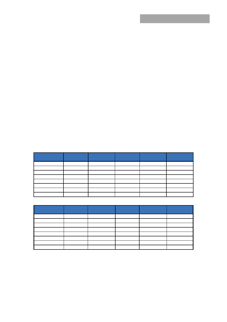
Table 7: Performance Vibration Qualification - All Axes
Frequency (Hz)
PSD Level
(G2/Hz)
Frequency (Hz)
PSD Level
(G2/Hz)
Frequency (Hz)
PSD Level
(G2/Hz)
10
1.14E-03
170
2.54E-03
690
1.03E-03
30
5.96E-03
230
3.70E-03
800
7.29E-03
40
9.53E-04
290
7.99E-04
890
1.00E-03
50
2.08E-03
340
1.12E-02
1070
2.67E-03
90
2.08E-03
370
1.12E-02
1240
1.08E-03
110
7.05E-04
430
8.84E-04
1550
2.54E-03
130
5.00E-03
490
1.54E-03
1780
2.88E-03
140
8.20E-04
560
5.62E-04
2000
5.62E-04
Table 8: Endurance Vibration Qualification - All Axes
Frequency (Hz)
PSD Level
(G2/Hz)
Frequency (Hz)
PSD Level
(G2/Hz)
Frequency (Hz)
PSD Level
(G2/Hz)
10
0.00803
170
0.01795
690
0.00727
30
0.04216
230
0.02616
800
0.05155
40
0.00674
290
0.00565
890
0.00709
50
0.01468
340
0.07901
1070
0.01887
90
0.01468
370
0.07901
1240
0.00764
110
0.00498
430
0.00625
1550
0.01795
130
0.03536
490
0.01086
1780
0.02035
140
0.0058
560
0.00398
2000
0.00398