20a analog microdlynx, Non-isolated dc-dc power modules, Data sheet – GE Industrial Solutions 20A Analog MicroDLynx User Manual
Page 13: Analog feature descriptions, Remote on/off, Monotonic start-up and shutdown, Startup into pre-biased output, Analog output voltage programming
GE
Data Sheet
20A Analog MicroDLynx
TM
: Non-Isolated DC-DC Power Modules
3Vdc –14.4Vdc input; 0.45Vdc to 5.5Vdc output; 20A Output Current
April 24, 2013
©2012 General Electric Company. All rights reserved.
Page 13
Analog Feature Descriptions
Remote On/Off
The 20A Analog MicroDLynx
TM
power modules feature an
On/Off pin for remote On/Off operation. Two On/Off logic
options are available. In the Positive Logic On/Off option,
(device code suffix “4” – see Ordering Information), the
module turns ON during a logic High on the On/Off pin and
turns OFF during a logic Low. With the Negative Logic On/Off
option, (no device code suffix, see Ordering Information), the
module turns OFF during logic High and ON during logic Low.
The On/Off signal should be always referenced to ground. For
either On/Off logic option, leaving the On/Off pin
disconnected will turn the module ON when input voltage is
present.
For positive logic modules, the circuit configuration for using
the On/Off pin is shown in Figure 39. When the external
transistor Q2 is in the OFF state, the internal transistor Q7 is
turned ON, which turn Q3 OFF which keeps Q6 OFF and Q5
OFF. This allows the internal PWM #Enable signal to be pulled
up by the internal 3.3V, thus turning the module ON. When
transistor Q2 is turned ON, the On/Off pin is pulled low, which
turns Q7 OFF which turns Q3, Q6 and Q5 ON and the internal
PWM #Enable signal is pulled low and the module is OFF. A
suggested value for R
pullup
is 20k
.
For negative logic On/Off modules, the circuit configuration is
shown in Fig. 40. The On/Off pin should be pulled high with an
external pull-up resistor (suggested value for the 3V to 14V
input range is 20Kohms). When transistor Q2 is in the OFF
state, the On/Off pin is pulled high, transistor Q3 is turned ON.
This turns Q6 ON, followed by Q5 turning ON which pulls the
internal ENABLE low and the module is OFF. To turn the
module ON, Q2 is turned ON pulling the On/Off pin low,
turning transistor Q3 OFF, which keeps Q6 and Q5 OFF
resulting in the PWM Enable pin going high.
Figure 39. Circuit configuration for using positive On/Off
logic.
Figure 40. Circuit configuration for using negative On/Off
logic.
Monotonic Start-up and Shutdown
The module has monotonic start-up and shutdown behavior
for any combination of rated input voltage, output current
and operating temperature range.
Startup into Pre-biased Output
The module can start into a prebiased output as long as the
prebias voltage is 0.5V less than the set output voltage.
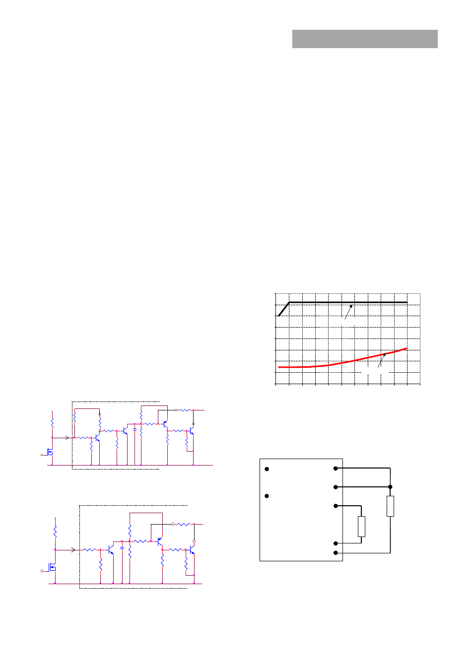
Analog Output Voltage Programming
The output voltage of the module is programmable to any
voltage from 0.6dc to 5.5Vdc by connecting a resistor
between the Trim and SIG_GND pins of the module. Certain
restrictions apply on the output voltage set point depending
on the input voltage. These are shown in the Output Voltage
vs. Input Voltage Set Point Area plot in Fig. 41. The Upper
Limit curve shows that for output voltages lower than 1V,
the input voltage must be lower than the maximum of
14.4V. The Lower Limit curve shows that for output voltages
higher than 0.6V, the input voltage needs to be larger than
the minimum of 3V. .
Figure 41. Output Voltage vs. Input Voltage Set Point Area
plot showing limits where the output voltage can be set
for different input voltages.
V
O
(+)
TRIM
VS─
R
trim
LOAD
V
IN
(+)
ON/OFF
VS+
SIG_GND
Caution – Do not connect SIG_GND to GND elsewhere in the
layout
Figure 42. Circuit configuration for programming output
voltage using an external resistor.
20K
Rpullup
I
20K
ON/OFF
+
20K
3.3V
470
VIN
20K
Q7
20K
100pF
4.7K
ENABLE
100K
DLYNX MODULE
47K
Q2
+VIN
20K
GND
20K
20K
2K
ON/OFF
Q6
Q5
V
Q3
_
ENABLE
470
4.7K
+VIN
20K
100K
2K
100pF
_
47K
GND
Q6
20K
Q2
+
DLYNX MODULE
V
Rpullup
Q3
ON/OFF
20K
I
ON/OFF
3.3V
Q5
20K
0
2
4
6
8
10
12
14
16
0.5
1
1.5
2
2.5
3
3.5
4
4.5
5
5.5
6
In
p
u
t
V
o
lt
a
g
e
(
v
)
Output Voltage (V)
Lower
Upper