Shhn000a3 series; dc-dc converter power modules, Datasheet, Test configurations – GE Industrial Solutions SHHN000A3 HAMMERHEAD Series User Manual
Page 6: Design considerations, Safety considerations, Input source impedance, Figure 7. input current versus input voltage, Figure 9. output ripple and noise test setup
GE
Datasheet
SHHN000A3 Series; DC-DC Converter Power Modules
9Vdc – 36Vdc input; +15V, -15V Dual Output, 0.3A 9W Output
December 6, 2013
©2013 General Electric Corporation.
All rights reserved.
Page 6
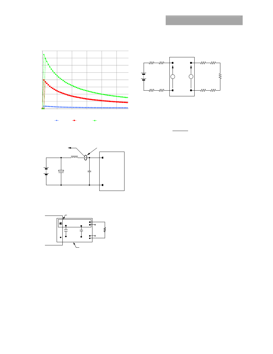
Figure 7. Input Current versus Input Voltage
Test Configurations
TO OSCILLOSCOPE
CURRENT PROBE
L
TEST
12μH
BA
T
T
E
R
Y
C
S
220μF
E.S.R.<0.1
Ω
@ 20°C 100kHz
33μF
Vin+
Vin-
NOTE: Measure input reflected ripple current with a simulated
source inductance (L
TEST
) of 12μH. Capacitor C
S
offsets
possible battery impedance. Measure current as shown
above.
Figure 8. Input Reflected Ripple Current Test Setup.
NOTE: All voltage measurements to be taken at the module
terminals, as shown above. If sockets are used then
Kelvin connections are required at the module terminals
to avoid measurement errors due to socket contact
resistance.
V
O
(+)
V
O
(
–
)
1uF
.
RESISTIVE
LOAD
SCOPE
COPPER STRIP
GROUND PLANE
10uF
Figure 9. Output Ripple and Noise Test Setup.
Vout+
Vout-
Vin+
Vin-
R
LOAD
R
contact
R
distribution
R
contact
R
distribution
R
contact
R
contact
R
distribution
R
distribution
V
IN
V
O
NOTE: All voltage measurements to be taken at the module
terminals, as shown above. If sockets are used then
Kelvin connections are required at the module terminals
to avoid measurement errors due to socket contact
resistance.
Figure 10. Output Voltage and Efficiency Test Setup.
η =
V
O
. I
O
V
IN
. I
IN
x
100
%
Efficiency
Design Considerations
Input Source Impedance
The power module shall be connected to a low ac-impedance
source. Highly inductive source impedance can affect the
stability of the power module. For the test configuration in
Figure 8, a 33μF electrolytic capacitor (ESR<0.7
Ω at 100kHz),
mounted close to the power module helps ensure the stability
of the unit
Safety Considerations
For safety-agency approval of the system in which the power
module is used, the power module shall be installed in
compliance with the spacing and separation requirements of
the end-use safety agency standard, i.e., UL 60950-1-3, CSA
C22.2 No. 60950-00, and VDE 0805 (IEC60950, 3
rd
Edition).
The input to these units is to be provided with a maximum 3A
fast-acting fuse in the ungrounded lead.
0
0.2
0.4
0.6
0.8
1
1.2
1.4
1.6
7
12
17
22
27
32
Input Curr
ent (A
)
Input Voltage (V)
Io min: 0A
Io mid: 0.15A
Io max: 0.3A