Shhn000a3 series; dc-dc converter power modules, Datasheet, General specifications – GE Industrial Solutions SHHN000A3 HAMMERHEAD Series User Manual
Page 4: Feature specifications
GE
Datasheet
SHHN000A3 Series; DC-DC Converter Power Modules
9Vdc – 36Vdc input; +15V, -15V Dual Output, 0.3A 9W Output
December 6, 2013
©2013 General Electric Corporation.
All rights reserved.
Page 4
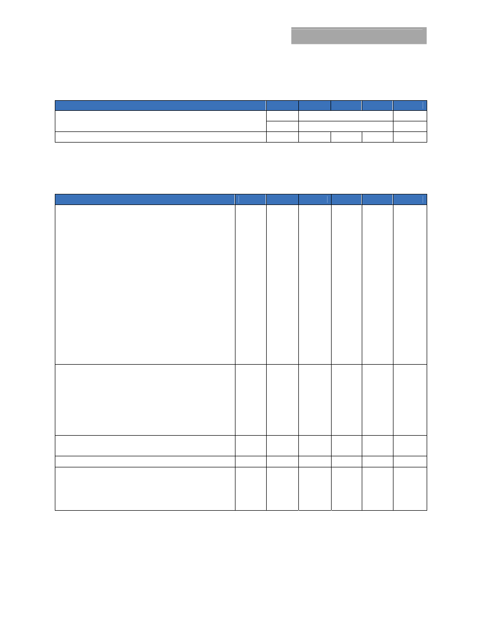
General Specifications
Parameter
Min
Typ
Max
Unit
Calculated Reliability based upon Telcordia SR-332 Issue 2: Method
I
Case 3
(V
IN
=24V
dc
, I
O
=80%xI
O, max
, T
A
=40°C, airflow = 200 LFM, 90% confidence)
FIT >=176.9
10
9
/Hours
MTBF >=5,652,118 Hours
Weight
⎯
8 (0.28)
⎯
g (oz.)
Feature Specifications
Unless otherwise indicated, specifications apply over all operating input voltage, resistive load, and temperature conditions. See
Feature Descriptions for additional information.
Parameter
Device
Symbol
Min
Typ
Max
Unit
Remote On/Off Signal Interface
(V
IN
=V
IN, min
to V
IN, max
; open collector or equivalent,
Signal referenced to V
IN-
terminal)
Negative Logic: device code suffix “1”
Logic Low = module On, Logic High = module Off
Logic Low - Remote On/Off Current (V
on/off
= -0.7V
dc
) All
I
on/off
⎯
⎯
0.15 mA
Logic Low - On/Off Voltage
All
V
on/off
-0.7
⎯
0.8 V
dc
Logic High Voltage (I
on/off
= 0A
dc
) All
V
on/off
2.0
⎯
V
IN
V
dc
Logic High maximum allowable leakage current
All
I
on/off
⎯
⎯
25
μA
Positive Logic: No device code suffix required
Logic Low = module Off, Logic High = module On
Logic Low - Remote On/Off Current (V
on/off
= -0.7V
dc
) All
I
on/off
⎯
⎯
0.15 mA
Logic Low - On/Off Voltage
All
V
on/off
-0.7
⎯
0.8 V
dc
Logic High Voltage (I
on/off
= 0A
dc
) All
V
on/off
2.0
⎯
V
IN
V
dc
Logic High maximum allowable leakage current
All
I
on/off
⎯
⎯
25
μA
Turn-On Delay and Rise Times for each output
(I
O
=80% of I
O, max
, T
A
=25°C)
Case 1: Input power is applied for at least 1second, and then the
On/Off input is set from OFF to ON (T
delay
= on/off pin transition until
V
O
= 10% of V
O, set
)
All
T
delay
Case1
⎯
25 ms
Case 2: On/Off input is set to Module ON, and then input power is
applied (T
delay
= V
IN
reaches V
IN, min
until V
O
= 10% of V
O,set
)
All
T
delay
Case2
⎯
25 ms
Output voltage Rise time (time for V
o
to rise from 10%
of V
o,set
to 90% of V
o, set
)
All T
rise
⎯
25 ms
Output Voltage Overshoot
3 %
V
O, set
(I
O
=80% of I
O, max
, V
IN
= 9 to 36V
dc
, T
A
=25°C)
Output Overvoltage Protection
All V
O, limit
140 %V
01,o2
Input Undervoltage Lockout
Turn-on Threshold
All
V
uv/on
8.5 V
dc
Turn-off Threshold
All
V
uv/off
7.5
V
dc
Hysteresis All
V
hyst
1.0 V
dc