Installation guide, Appendix a: mechanical installation, Aspmeter – GE Industrial Solutions ASPMETER Install User Manual
Page 7
TM
ASPMETER
INSTALLATION GUIDE
Z206024-0B
PAGE 7
©2011 For technical support please contact
10111
DET-756
our GE tech support team at 1-800-GE-1-STOP (1-800-431-7867)
APPENDIX A:
MECHANICAL INSTALLATION
Observe handling precautions for static sensitive
devices to avoid damage to the circuitry which
would not be covered under the factory warranty.
Disconnect power to the electrical panel and lock it out.
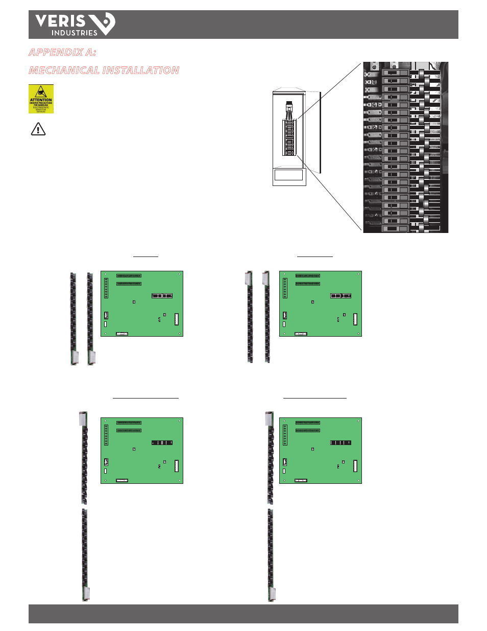
1. Install the current sensor strips in the panel (Figure 1).
2. Arrange the sensor strips in one of the four configurations shown in Figure 2.
Adjust orientation of the circuit numbers in the field during commissioning by
writing to Modbus Register 6 or use free configuration software at www.veris.
com.
Figure 1
CTs accept a maximum #2 AWG (0.384” O.D.)
wire with THHN insulation.
Use this gauge wire or smaller for 100 A circuits.
E30 CURRENT SENSOR STRIP
E30 CURRENT SENSOR STRIP
20
20
20
20
20
20
20
20
20
2020
20
20
20
20
20
20
20
20
20
20
20
1
5
9
13
17
21
25
29
33
37
41
3
7
11
15
19
23
27
31
35
39
2
6
10
14
18
22
26
30
34
38
42
4
8
12
16
20
24
28
32
36
40
A
B
1
5
9
13
17
21
25
29
33
37
41
3
7
11
15
19
23
27
31
35
39
2
6
10
14
18
22
26
30
34
38
42
4
8
12
16
20
24
28
32
36
40
A
B
1
3
5
7
9
11
13
15
17
19
21
2
4
6
8
10
12
14
16
18
20
22
24
26
28
30
32
34
36
38
40
42
23
25
27
29
31
33
35
37
39
41
2
6
10
14
18
22
26
30
34
38
42
4
8
12
16
20
24
28
32
36
40
1
5
9
13
17
21
25
29
33
37
41
3
7
11
15
19
23
27
31
35
39
A
B
A
B
A
B
A
B
A
B
A
B
A
B
Top Feed
Bottom Feed
Single Row: Sequential
Single Row: Odd/Even
Register 6
Value = 0
(Default)
Register 6
Value = 1
Register 6
Value = 2
Register 6
Value = 3
Figure 2