Installation guide, Data output, Blink codes for status led – GE Industrial Solutions ASPMETER Install User Manual
Page 3: Commissioning, Aspmeter
TM
ASPMETER
INSTALLATION GUIDE
Z206024-0B
PAGE 3
©2011 For technical support please contact
10111
DET-756
our GE tech support team at 1-800-GE-1-STOP (1-800-431-7867)
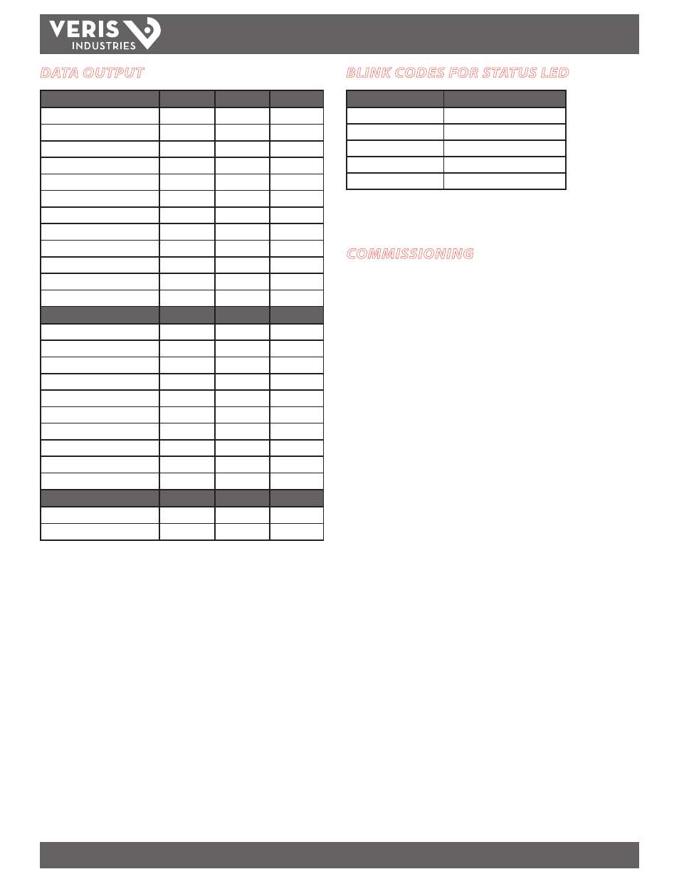
DATA OUTPUT
Monitoring at Mains
ASPMETERA ASPMETERB ASPMETERC
Current per phase
Max. current per phase
Current demand per phase
Max. current demand per phase
Energy (kWh) per phase
Real Power (kW) per phase
Apparent Power (kVA)
Power factor total *
Power factor per phase
Voltage - L-L and average
Voltage - L-N and average
Frequency (phase A)
Monitoring at Branch Circuit
Current
Max. current
Current demand
Max. current demand
Real power (kW)
Real power (kW) demand
Real power (kW) demand max.
Energy (kWh) per circuit
Power factor
Apparent Power (kVA)
Modbus Alarms
Voltage over/under
Current over/under
* Based on a 3-phase breaker rotation.
BLINK CODES FOR STATUS LED
Color and Pattern
Status Description
Green, once per second
Normal operation
Amber, once per second
Volts or Amps clipping
Amber, twice per second
Invalid firmware image
Amber, three per second
Incorrect strips or strip order
Red, solid or blink
Device Failure
COMMISSIONING
1. Install according to instructions in Appendix A.
1. Provide control power to main circuit board.
2. Configure installation mode using Modbus Register 6.
3. Configure CT scaling.
4. Configure alarms.
5. Configure demand.
Download the free E3x Configuration Tool from www.veris.com to commission the
ASPMETER for operation. (Click path: www.veris.com >> “Design Resources” >>
“Protocol Info” >> “Modbus” >> “E3x Configuration Tool”)