Installation guide, Wiring, Aspmeter – GE Industrial Solutions ASPMETER Install User Manual
Page 4: Wire 4-wire 2-wire example, Shield rx- tx- rx+ tx+ tx- tx
TM
ASPMETER
INSTALLATION GUIDE
Z206024-0B
PAGE 4
©2011 For technical support please contact
10111
DET-756
our GE tech support team at 1-800-GE-1-STOP (1-800-431-7867)
WIRING
Power must be disconnected and locked out before making any wiring connections.
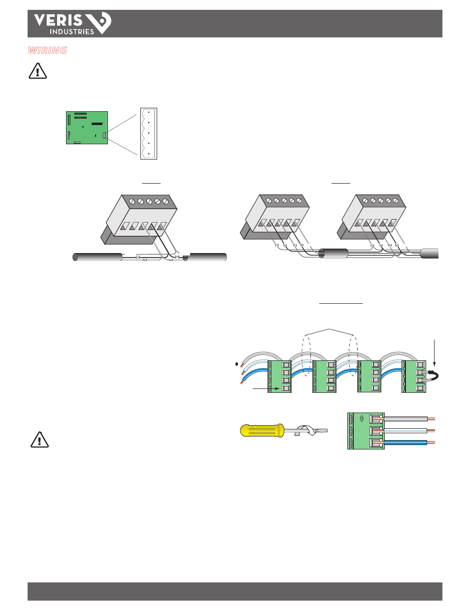
Connect 2-wire or 4-wire Modbus RS-485 daisy chain network (Figures 9 and 10).
Figure 9
Figure 10
SHIELD
RX- TX-
RX+ TX+
TX-
TX+
Master or Slave
SHLD
TX+
TX+
RX+
TX–
TX-
RX-
SHIELD
SHIELD
Master
Slave
SHLD
TX+
TX+
RX+
TX–
TX-
RX-
SHIELD
SHLD
TX+
TX+
RX+
TX–
TX-
RX-
SHIELD
2-Wire
4-Wire
2-Wire Example
Figure 11
–
+
Belden 1120A or
equivalent
120 Ω terminator
on last device of
daisy chain
Not Used
WARNING: After wiring the RS-485 cable, remove all
scraps of wire or foil shield from the electrical panel.
Wire scraps coming into contact with high voltage
conductors could be DANGEROUS!
–
+
1. Mechanically secure the RS-485 cable where it enters the electrical panel.
2. Connect all RS-485 devices in a daisy-chain fashion, and properly terminate the
chain (Figure 11).
3. Shield the RS-485 cable using twisted-pair wire, such as Belden 1120A. The cable
must be voltage-rated for the installation.
4. When tightening terminals, ensure that the correct torque is applied: 0.5 to 0.6
N·m (0.37 to 0.44 ft·lb ) for connectors on main board, 0.22 to 0.26 N·m (0.16 to
0.19 ft·lb) for connectors on adapter boards (Figure 12).
Figure 12