Communication environment, Modbus message frames, Smr2 modbus user manual – GE Industrial Solutions Record Plus FG600 SMR2 Modbus User Manual
Page 6: Master’s query, Slave’s response, Examples
SMR2 Modbus User Manual
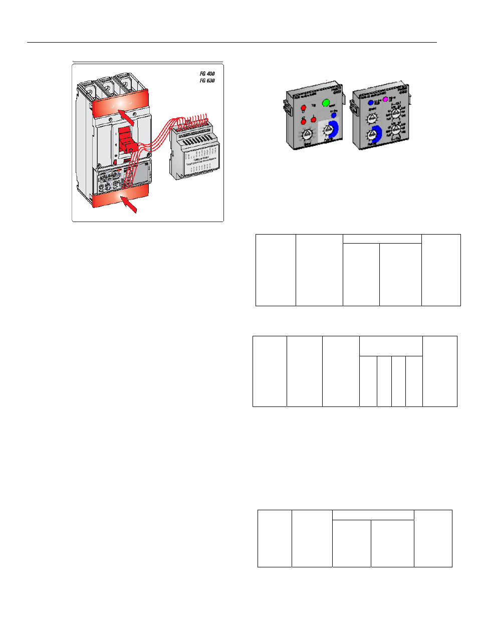
Figure2. Connection between Breaker and FAMECM
module
3
Communication Environment
• The trip unit is always the slave and cannot
initiate communication
• All the registers are read-only
• Hardware layer
RS485: Data moves serially on a 2-wire differential line
(used for TX as well as Rx i.e.; half- duplex)
N-8-1, no parity, 1 start bit, 8 data bits & 1 stop bit (10
bits per character)
• Communication Protocol
RTU Modbus Master-Slave protocol Command-
response (half-duplex) Min delay between messages is
3.5 char time Max delay within message is 1.5 char
time.
Slave Response time: minimum 3.5 char;
maximum 50mS + 1mS per register
Register order: MSB first, then LSB
• In the presence of a communication
module on Trip unit
A pair of rotary switch decides the Modbus address (0
to 255)
A pair of slide switch decides the baud rate (2400, 4800,
9600 or 19200bps). These switches are available on the
backside of the module
• In the absence of a communication
module on Trip unit
The communication happens at 19200bps with a
Modbus address of 100
Figure3. Communication modules used with trip unit
Modbus Message Frames
Master’s Query
Data (n bytes)
Slave
Address
(1 byte)
Function
Code
(1 byte)
Start
Address
(2 bytes)
No. of
Registers
(2 bytes)
CRC
(2 bytes)
Slave’s Response
Data (n bytes)
Slave
Address
(1byte)
Functio
n Code
(1 byte)
Number
of Bytes
(1 byte)
Byte1
Byte2
..
Byte n
CRC
(2bytes)
Examples :
Read Holding Registers (Function Code 03)
Use this command to read setpoint or fixed value
registers. It specifies the starting register and the
number of registers to be read. Read the registers 3010-
3012 from device 100:
Data
(n bytes)
Slave
Addres
s
(1
byte)
Function
Code
(1 byte)
Start
Address
(2
bytes)
No. of
Registers
(2
bytes)
CRC
(2
bytes)