Dynamic value registers, Smr2 modbus user manual – GE Industrial Solutions Record Plus FG600 SMR2 Modbus User Manual
Page 10
SMR2 Modbus User Manual
7
Test mode
-- RW
5 150/160
6 250/250
7 400/400
8 600/630
9 800/800
10 1200/1250
11 1600/1600
12 350
13 500
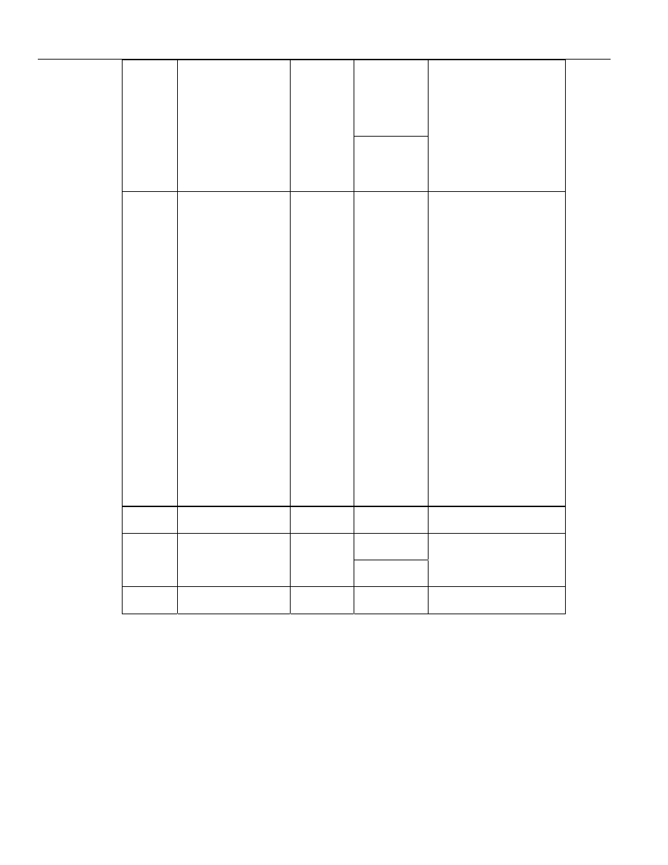
0007
Information Memory
Option Byte 1
Bitmappe
d 0 to
FFFFh
Normal
mode--- RO
___________
Test mode
--- RW
b0 Instantaneous
0
enabled
1 disabled
b1 Short Time
0
enabled
1
disabled
b2 Long Time
0
enabled
1
disabled
b3 Watchdog
0
enabled
1
disabled
b4 Zone Select Interlock
0
enabled
1
disabled
b5 50-60/400 Hz
Operation
0 50/60 Hz
1 400 Hz
b6 Thermal Watchdog
0 disabled
1-99 enabled
b7 Unused
0008
Software revision
number
0000 to
9999
RO
4 digit BCD
Normal
mode --- RO
0009
Product revision
number
0000 to
9999
Test mode
--- RW
4 digit BCD
0010
Max Number of
events stored
Always 8
RO
Unsigned Int
Dynamic Value Registers
Actual value registers start at 1000, read by Function
Code 04.All the dynamic value registers are 32-bit in
length. Hence, query of any variable results in two
Modbus register reads, each of 16-bit length. Even
numbered register holds upper-16 bits; Odd numbered
register holds lower –16 bits
Example: To find out Phase-A SOS, A Modbus query to
read 1002 and 1003 registers need to be sent to SMR2
by the master.
There are 32 bits in this data. The upper-16 bits would
appear in register 1002 and lower-16 bits in register
1003 as a part of the response.