GE Industrial Solutions MicroVersaTrip PM User Manual
Page 28
MicroVersaTrip Plus™ and MicroVersaTrip PM™ Trip Units
Chapter 2. Setup Mode
18
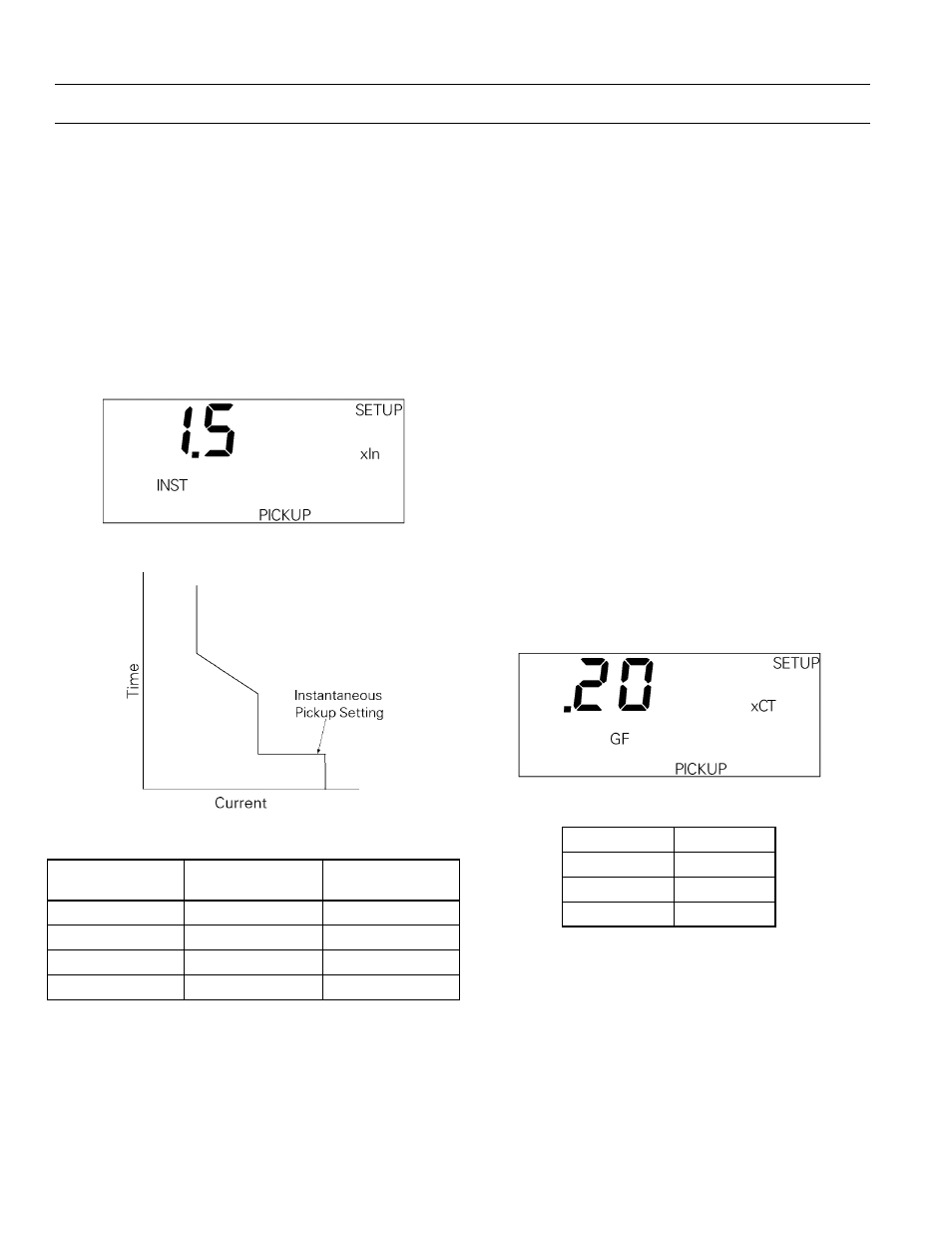
Instantaneous Pickup
Instantaneous overcurrent protection, with Trip Unit
display illustrated in Figure 19, causes an immediate
breaker trip when the chosen current level is
reached. The pickup value may be set in steps of 0.5
xIn from 1.5 xIn to a maximum dependent on the
frame size and the presence of the short-time
function, as listed in Table 13.
Note the difference from short-time pickup, which is
based on a multiple of
x L T . The time-current
characteristic is shown in Figure 20.
Figure 19. Trip Unit display for instantaneous pickup.
Figure 20. Instantaneous overcurrent protection set point.
F
F
F
Frrrraa
a
am
m
m
meee
e M
M
M
Maa
a
ax
x
x
x.... A
A
A
Am
m
m
mp
p
p
p
R
R
R
Raa
a
attttiiiin
n
n
ng
g
g
g
SS
S
Seee
ettttp
p
p
po
o
o
oiiiin
n
n
nttttssss
W
W
W
Wiiiitttth
h
h
ho
o
o
ou
u
u
utttt SSS
ST
T
T
T
SS
S
Seee
ettttp
p
p
po
o
o
oiiiin
n
n
nttttssss
W
W
W
Wiiiitttth
h
h
h SSS
ST
T
T
T
2000
1.5–10.0
xIn
1.5–15.0
xIn
3200
1.5–10.0
xIn
1.5–13.0
xIn
4000
1.5–9.0
xIn
1.5–9.0
xIn
5000
1.5–7.0
xIn
1.5–7.0
xIn
Table 13. Instantaneous pickup settings for various frame sizes
with and without the short-time function.
On Trip Units with the user-selectable switchable
instantaneous overcurrent and ground-fault option,
X, an additional value of
OFF
appears at the end of
the listing of numerical values. Choose this setting to
disable instantaneous protection. The instantaneous
OFF
selection is interlocked with short-time pickup,
so that only one function can be turned off at a time.
High-Range Instantaneous Overcurrent
Protection
High-range instantaneous overcurrent protection
has a fixed trip setting equal to the breaker frame’s
short-time withstand rating,
H, with pickup tolerance
+0%, –20%. When this option is installed, skip pro-
gramming of instantaneous pickup and go on to the
next function by pressing
SELECT
.
Ground-Fault Pickup
The trip unit display for ground-fault pickup is
shown in Figure 21. This function sets the pickup
current for ground-fault protection. The available
settings are listed in Table 14 as multiples of
xCT the
current sensor rating, in steps of 0.01
xCT. The
maximum value is limited to 1200 A. Figure 22
illustrates the time-current curve for ground-fault
pickup.
Figure 21. Trip Unit display for ground-fault pickup.
SS
S
Seee
en
n
n
nsssso
o
o
orrrr,,,, A
A
A
A
SS
S
Seee
etttt P
P
P
Po
o
o
oiiiin
n
n
nttttssss
150–2000
0.20–0.60
2500–3200
0.20–0.37
4000
0.20–0.30
Table 14. Ground-fault pickup settings, as a function of sensor
rating.