GE Industrial Solutions MicroVersaTrip PM User Manual
Page 27
MicroVersaTrip Plus™ and MicroVersaTrip PM™ Trip Units
Chapter 2. Setup Mode
17
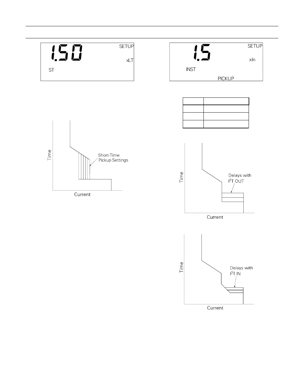
Figure 14. Trip Unit display for short-time pickup coupled with
long-time pickup.
The time-current curve for short-time pickup is
shown in Figure 15.
Figure 15. Time-current curve illustrating short-time pickup.
Short-Time Delay
The Trip Unit display for short-time delay is shown
in Figure 16. This function delays the breaker trip on
a short-time trip. The choices of time-delay bands
are listed in Table 12. The delay with
I2T IN
is for a
current of 600% of
xLT at the lower limit of the
band. The delay with
I2T OUT
is for the lower limit of
each band.
On ANSI Trip Units ordered with the user-selectable,
switchable instantaneous overcurrent and ground-
fault option, “X,” an additional value of
OFF
appears
at the end of the delay band settings. Choosing
OFF
disables short-time protection. The short-time
OFF
band is interlocked with instantaneous pickup, so
that only one function can be turned off at a time.
The
I2T OUT
function, illustrated in Figure 17, estab-
lishes a constant time delay.
I2T IN
biases the delay
with a constant slope, as shown in Figure 18.
Figure 16. Trip Unit display for short-time delay.
B
B
B
Baa
a
an
n
n
nd
d
d
d
T
T
T
Tiiiim
m
m
meee
e D
D
D
Deee
ellllaa
a
ayyyyssss,,,, sssseee
eccc
c
1
0.10
2
0.21
3
0.35
Table 12. Lower-limit delays for
I2T OUT
short-time delay bands.
Figure 17. Time-current curve for short-time delay with
I2T OUT
.
Figure 18. Time-current curve for short-time delay with
I2T IN
.