Feature descriptions (continued), Output voltage programming, Table 1 – GE Industrial Solutions Austin MicroLynx II 12V SIP User Manual
Page 13: Voltage margining, Feature descriptions
Data Sheet
January 18, 2010
Austin MicroLynx
II
TM
12V SIP Non-isolated Power Modules:
8.3 – 14Vdc input; 0.75Vdc to 5.5Vdc Output; 6A output current
Feature Descriptions
(continued)
Output Voltage Programming
The output voltage of the Austin MicroLynx
TM
II 12V
SIP can be programmed to any voltage from 0.75Vdc
to 5.5Vdc by connecting a resistor (shown as Rtrim in
Figure 30) between Trim and GND pins of the
module. Without an external resistor between Trim
and GND pins, the output of the module will be
0.7525Vdc. To calculate the value of the trim resistor,
Rtrim
for a desired output voltage, use the following
equation:
Ω
⎥⎦
⎤
⎢⎣
⎡
−
−
=
1000
7525
.
0
10500
Vo
Rtrim
Rtrim
is the external resistor in Ω
Vo is the desired output voltage
For example, to program the output voltage of the
Austin MicroLynx
TM
12V module to 1.8V, Rtrim is
calculated as follows:
⎥⎦
⎤
⎢⎣
⎡
−
−
=
1000
7525
.
0
8
.
1
10500
Rtrim
Ω
=
k
Rtrim
024
.
9
V
O
(+)
TRIM
GND
R
trim
LOAD
V
IN
(+)
ON/OFF
Figure 30. Circuit configuration to program
output voltage using an external resistor
Table 1 provides Rtrim values for most com
output voltages.
mon
Table 1
V
O, set
(V)
Rtrim (
KΩ)
0.7525 Open
1.2 22.46
1.5 13.05
1.8 9.024
2.5 5.009
3.3 3.122
5.5 1.472
Using 1% tolerance trim resistor, set point tolerance
of ±2% is achieved as specified in the electrical
specification. The POL Programming Tool, available
at
www.lineagepower.com
under the Design Tools
section, helps determine the required external trim
resistor needed for a specific output voltage.
The amount of power delivered by the module is
defined as the voltage at the output terminals
multiplied by the output current. When using the
trim feature, the output voltage of the module can
be increased, which at the same output current
would increase the power output of the module.
Care should be taken to ensure that the maximum
output power of the module remains at or below the
maximum rated power (P
max
= V
o,set
x I
o,max
).
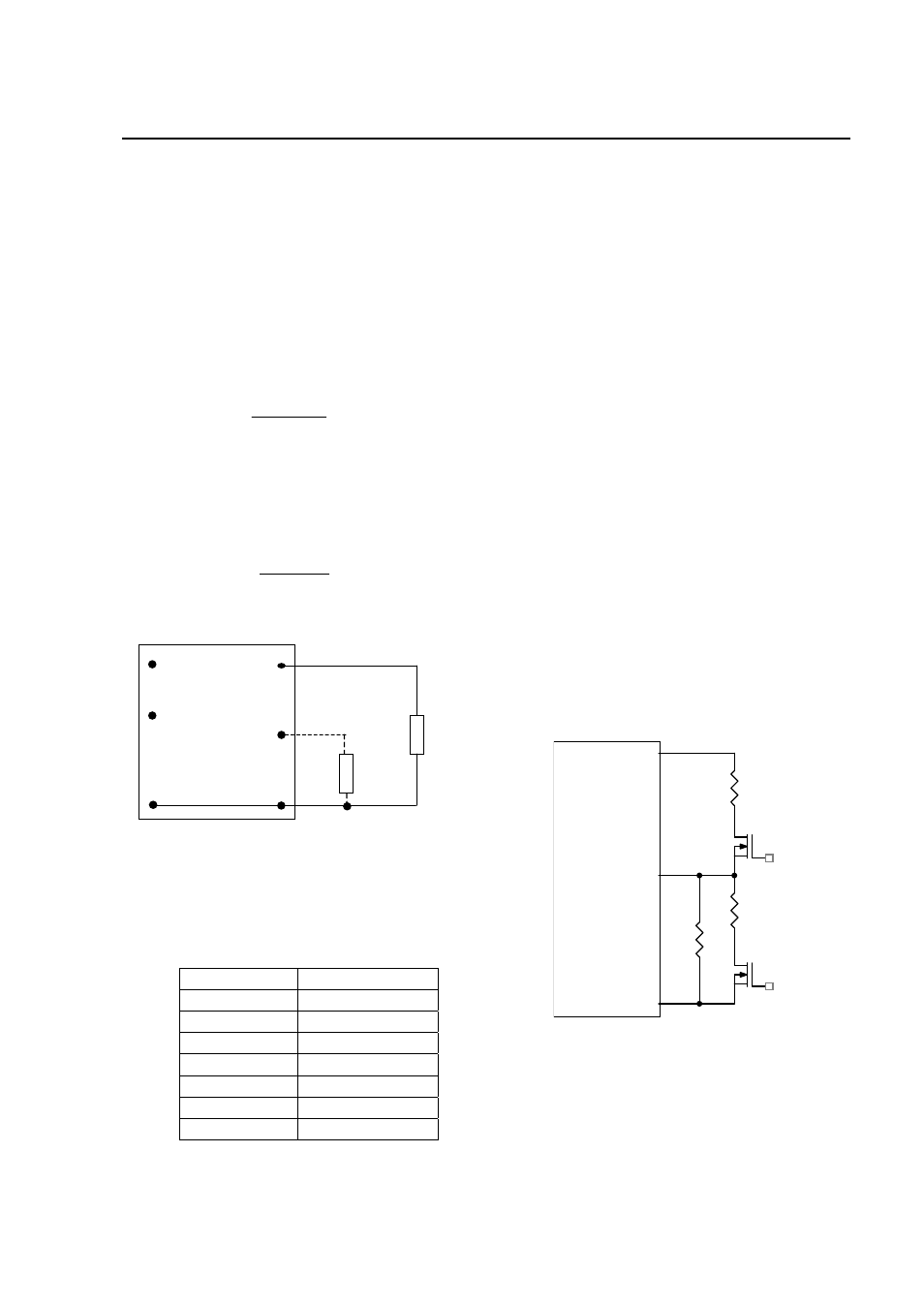
Voltage Margining
Output voltage margining can be implemented in
the Austin MicroLynx
TM
II modules by connecting a
resistor, R
margin-up
, from Trim pin to ground pin for
margining-up the output voltage and by connecting
a resistor, R
margin-down
, from Trim pin to Output pin.
Figure 31 shows the circuit configuration for output
voltage margining. The POL Programming Tool,
available at
www.lineagepower.com
under the
Design Tools section, also calculates the values of
R
margin-up
and R
margin-down
for a specific output
voltage and % margin. Please consult your Lineage
Power technical representative for additional details
Vo
Austin Lynx or
Lynx II Series
GND
Trim
Q1
Rtrim
Rmargin-up
Q2
Rmargin-down
Figure 31. Circuit Configuration for margining
Output voltage.
LINEAGE
POWER
13